Evaporator A-Coil, Cased, Multipoise for R-454B Refrigerant: Installation Instructions
Manufacturer reserves the right to change, at any time, specifications and designs without notice and without obligations.
6
A210138A
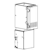
Fig. 11 – TXV Bulb
Condensate Drain
Units are equipped with primary and secondary 3/4" FPT drain
connections. It is recommended that PVC fittings be used on the plastic
condensate pan. Do not over-tighten. Finger-tighten plus 1-1/2 turns. For
proper condensate line installation review Fig. 12 and Fig. 13.
NOTE: When connecting condensate drain lines, avoid blocking filter
access panel, thus preventing filter removal. After connection, prime
both primary and secondary condensate traps.
IMPORTANT: The owner of the structure must be informed that when
condensate flows from the secondary drain, the unit requires servicing or
else water damage will occur.
Optionally, a float switch may be used in lieu of a secondary drain. If so,
make sure the float switch is installed so that it will trip before the water
exits the weep hole between the drain pans. The float switch may be
installed in the primary drain line or inside the pan. If installing in the
secondary drain, make sure the float switch is below the exit of the drain.
NOTE: Do not install the float switch at the same level as the secondary
drain exit.
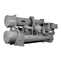
Install traps in the condensate lines as close to the coil as possible
(Fig. 12). Make sure that the outlet of each trap is below its connection
to the condensate pan to prevent condensate from overflowing the drain
pan. Prime all traps and test for leaks.
A03002A
Fig. 12 – Recommended Condensate Trap
A03013
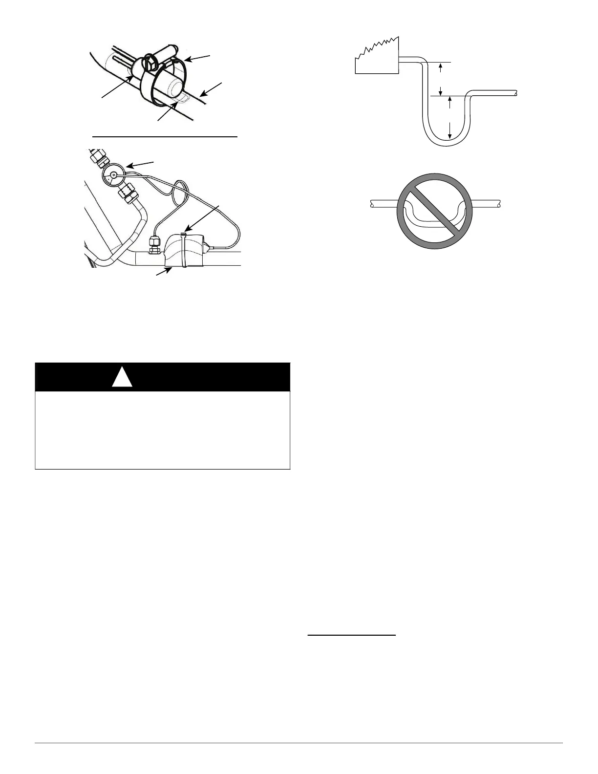
Fig. 13 – Insufficient Condensate Trap
Condensate drain lines should be pitched downward at a minimum slope
of 1" for every 10 feet of length. Consult local codes for additional
restrictions or precautions.
NOTE: If unit is located in or above a living space, where damage may
result from condensate overflow, a field−supplied, external condensate
pan should be installed underneath the entire unit, and a secondary
condensate line (with appropriate trap) should be run from the unit into
the pan. Any condensate in this external condensate pan should be
drained to a noticeable place. As an alternative to using an external
condensate pan, some localities may allow the running of a separate 3/4
inch (19 mm) condensate line (with appropriate trap) per local code to a
place where the condensate will be noticeable. The owner of the
structure must be informed that when condensate flows from secondary
drain or external condensate pan, the unit requires servicing or water
damage will occur. To further protect against water damage, install a
float switch to shut the unit off if the water in the secondary pan gets too
high.
ELECTRICAL CONNECTIONS
This evaporator includes low voltage (24V) electrical equipment. ALL
equipment must be installed for proper operation of the system and to
prevent hazardous conditions per UL60335-2-40.
Leak Dissipation System
This unit is required to be installed with an R-454B leak detection and
dissipation system (included with the evaporator coil). This system is
comprised of a refrigerant sensor, sensor wire harness, leak dissipation
control board, dissipation board housing, and power wire harness.
Failure to install this system will result in potentially hazardous
conditions and improper equipment operation, and void all system
warranties and liabilities.
Refrigerant Sensor
The 5V refrigerant sensor will be factory installed inside of the
evaporator coil. For proper operation, the sensor must remain in the
factory installed location inside of the evaporator coil. Verify that the
refrigerant sensor is installed in the correct location and orientation
(Fig. 14).
CAUTION
!
UNIT OR PRODUCT DAMAGE HAZARD
Failure to follow this caution may result in unit or product damage.
BOTH primary and secondary drain lines should be installed and
include properly sized condensate traps. Shallow, running traps are
inadequate and do not allow proper condensate drainage. Use pipe
dope. Do not over-torque. Hand tighten plus 1-1/2 turns.
Insulation
Wire
Tie
TXV
TXV Insulation Wrap
Metal Clamp ONLY
Sensing Bulb
Sensing Bulb Indentation
Vapor Line
2” MIN
(51 mm)
UNIT
2” MIN
(51 mm)
PRIMARY DRAIN
DO NOT USE SHALLOW RUNNING TRAPS!