FMC4X, FMC4Z: Installation Instructions
Manufacturer reserves the right to change, at any time, specifications and designs without notice and without obligations.
2
For Conversion to Horizontal Return:
1. Remove the back panel from the casing assembly.
2. Using the dimples on the back of the casing as a guide, pre-cut the
insulation and remove to prevent damage that may occur while
cutting the new return opening.
3. Cut the return opening into the sheet metal using the dimples as a
guide.
4. Reinstall the back panel on to the casing.
5. Field fabricate and mount a cover panel to completely seal bottom
return opening of the fan coil.
After Mounting Unit, Install Refrigeration Tubing as Follows:
1. Route tubing to connection points.
2. Remove plugs from liquid and vapor lines.
3. Wrap the TXV with a wet rag to prevent overheating.
4. Shield casing insulation with sheet metal in the area you will be
brazing.
5. Braze connections using either silver bearing or non-silver bearing
brazing material. Do not use soft solder (materials which melt
below 800°F / 427°C). Consult local code requirements. Always
flow nitrogen through the system refrigerant lines while brazing.
6. Pressurize system and leak test. Repeat procedure until leak free.
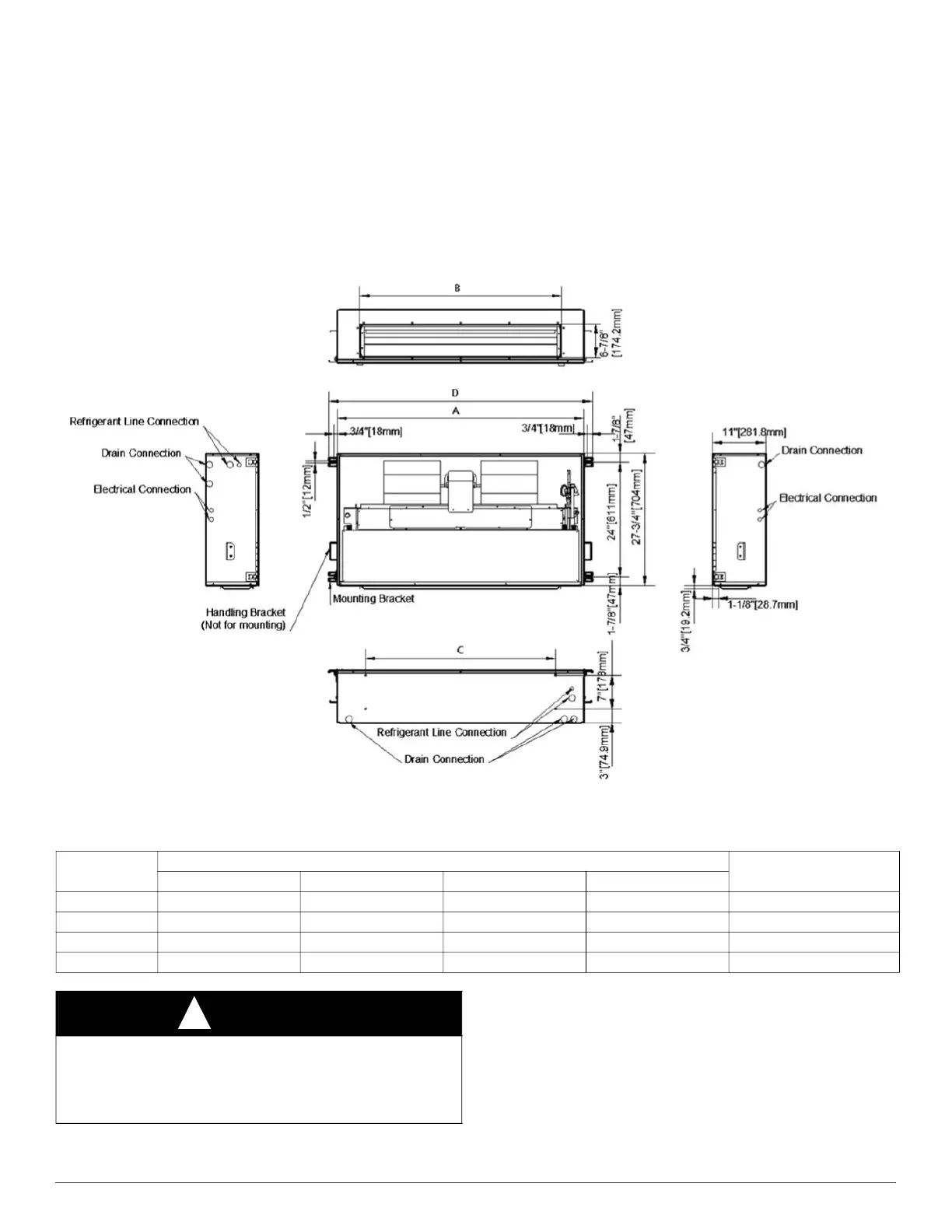
A170308
Fig. 1 – Dimensional Drawing
Supply-Air Connections
When fan coil is equipped with an electric heater, install air ducts in
accordance with standards 90A and 90B of National Fire Protection
Association (NFPA). Use of flexible connectors between ductwork and
unit will prevent transmission of vibration. When electric heater is
installed, use heat-resistant material for a flexible connector between
ductwork and unit air discharge connection. Ductwork passing through
unconditioned space must be insulated and covered with a vapor barrier.
NOTE: Local codes may limit this unit to single-level applications.
Table 1 – Dimensional Data
Model Size
Dimensions- inches [mm]
Unit Operating Weight
lbs (kg)
A B C D
18
39-3/4 [1010] 30-3/8 [771] 28 [711] 43-3-8 [1101] 115 (52)
24
39-3/4 [1010] 30-3/8 [771] 28 [711] 43-3-8 [1101] 115 (52)
30
51-3/4 [1315] 42-1/6 [1071] 40 [1016] 55-3-8 [1406] 137 (62)
36
51-3/4 [1315] 42-1/6 [1071] 40 [1016] 55-3-8 [1406] 137 (62)
CAUTION
!
ENVIRONMENTAL HAZARD
Failure to follow this caution may result in environmental damage.
Do not vent refrigerant to atmosphere. Recover during system repair or
final unit disposal.