FMC4X, FMC4Z: Installation Instructions
Manufacturer reserves the right to change, at any time, specifications and designs without notice and without obligations.
5
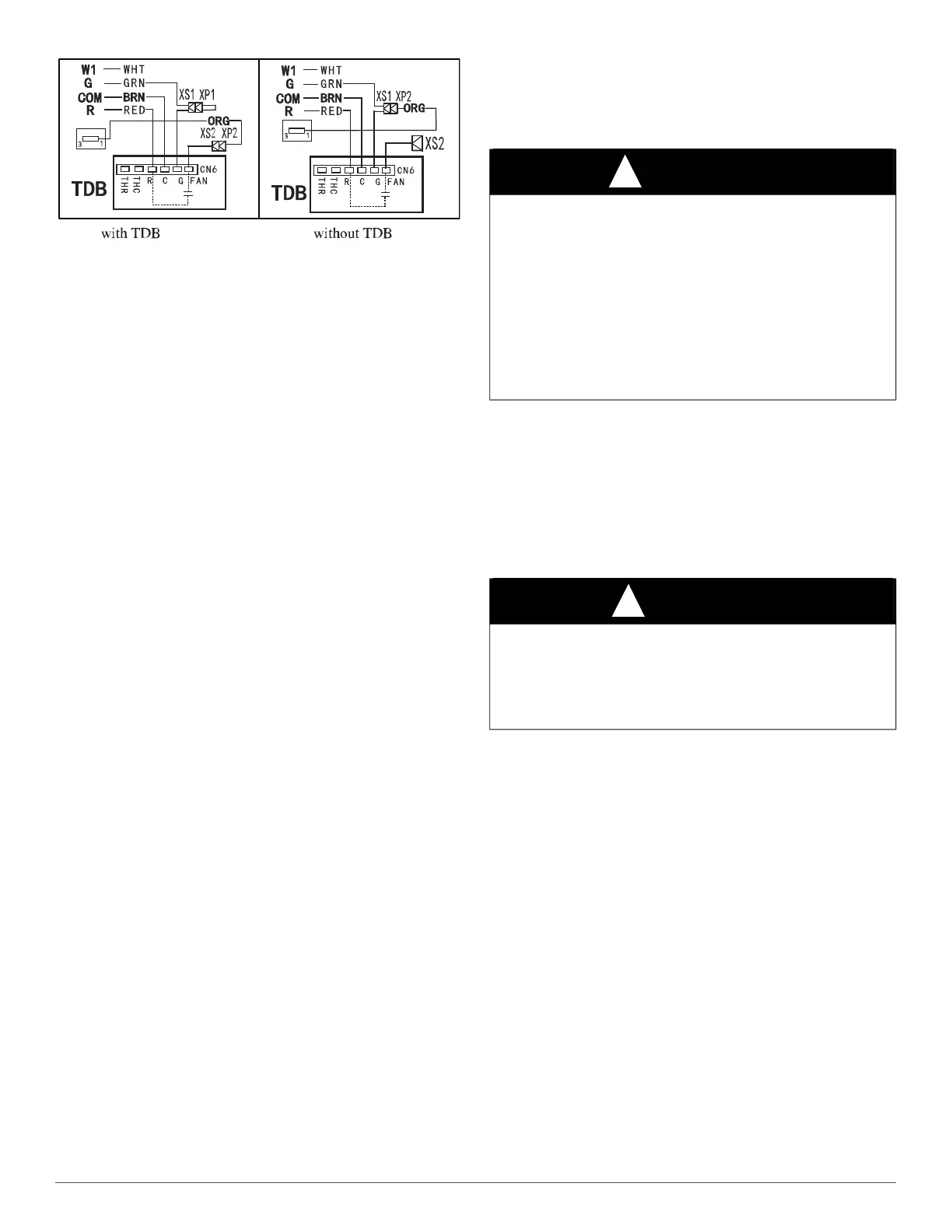
A210094
Fig. 6 – Wiring Layout FMC4X PSC Motor Disable Time Delay
TXV
The TXVs are preset at the factory and do not need adjustment for
reliable operation.
START-UP
Refer to outdoor unit Installation Instructions for system start-up
instructions and refrigerant charging method details.
SEQUENCE OF OPERATION
The following sequence of operation is based on units installed with
ECM\PSC motor and Time Delay Board (TDB).For units with ECM
motor, the off-delay is programmed into the motor. Follow Table 2,
ECM Motor Speed Taps & the corresponding blower off delays for each
speed tap. PSC models are factory wired with TDB active. Follow Fig. 6
to disable blower off time delay. When wired in this configuration no
blower off-delay will occur in any mode.
CONTINUOUS FAN
Thermostat closes R to G. G energizes and completes circuit to indoor
blower motor. When G is de-energized, there is a 90 sec blower
off-delay.
COOLING MODE
Thermostat energizes R to G, R to Y, and R to O (heat pump only). G
energizes and completes indoor blower motor. Y energizes outdoor unit
(O is energized for heat pump). When cooling call is satisfied, G is
de-energized, there is a 90 sec blower off-delay.
HEAT PUMP HEATING MODE
Thermostat energizes R to G and R to Y. G energizes and completes
circuit to indoor blower motor. When heating call is satisfied, G is
de-energized, there is a 90 sec blower off-delay.
HEAT PUMP HEATING WITH AUXILIARY
ELECTRIC HEAT
Thermostat energizes R to G, R to Y, and R to W1. G energizes and
completes circuit to indoor blower motor. W1 energizes electric heat
relay(s) which completes circuit to heater element(s). When W1 is
de-energized, electric heat relay(s) open, turning off heater elements.
When G is de-energized there is a 90 sec blower off-delay.
ELECTRIC HEAT OR EMERGENCY HEAT MODE
Thermostat energizes R to W1. W1 energizes electric heat relay(s) which
completes circuit to heater element(s). Blower motor is energized
through normally closed contacts on fan relay. When W1 is
de-energized, electric heat relay(s) opens, there is no blower off-delay.
CARE AND MAINTENANCE
For continuing high performance and to minimize possible equipment
failure, it is essential that periodic maintenance be performed on this
equipment. The only required maintenance that may be performed by the
consumer is filter maintenance.
The minimum maintenance requirements for this equipment are as
follows:
1. Inspect and clean or replace air filter each month or as required.
2. Inspect cooling coil, drain pan, and condensate drain each cooling
season for cleanliness. Clean as necessary.
3. Inspect blower motor and wheel for cleanliness each heating and
cooling season. Clean as necessary.
4. Inspect electrical connections for tightness and controls for proper
operation each heating and cooling season. Service as necessary.
NOTE: The installing technician should explain system operation to the
consumer with particular emphasis on indoor fan coil operation sounds
and filter maintenance.
WARNING
!
ELECTRICAL OPERATION HAZARD
Failure to follow this warning could result in personal injury or death.
Disconnect all power to unit before servicing field wires or removing
control package. The disconnect (when used) on access panel does not
allow safe service to all other parts of unit.
If unit does not have a disconnect, disregard the foregoing. Instead,
make sure that a disconnecting means is within sight from, and is
readily accessible from, the unit.
Disconnect all electrical power to unit before performing any
maintenance or service on it. Lock out and tag switch with a suitable
warning label.
CAUTION
!
CUT HAZARD
Failure to follow this caution may result in personal injury.
Sheet metal parts may have sharp edges or burrs. Use care and wear
appropriate protective clothing, safety glasses and gloves when
handling parts.