©2021
Catalog No: 496 01 8202 01
Edition Date: 08/21
Replaces: 496 01 8202 00
FMC4X, FMC4Z: Installation Instructions
Manufacturer reserves the right to change, at any time, specifications and designs without notice and without obligations.
8
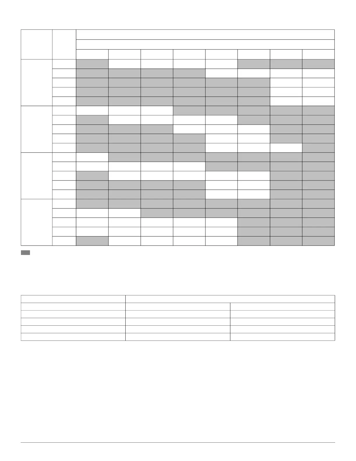
- Shaded boxes represent airflow outside the required 300-450 cfm/ton.
NOTES:
1. Airflow data is without filter or electric heat accessory. Heater adds 0.05-in. static.
2. Use dry coil data for determining electric heater airflow.
3. Use wet coil data for determining cooling airflow.
4. Accessory louver panel adds 0.05-in. Static.
Table 6 – Airflow Performance (CFM) — Use for Selecting Heat Pump Speed of ECM Motor (Cased, Bottom Return)
Model
Motor
Speed
CFM Wet Coil w ithout Filter or Electric Heat, Cased, Bottom Return
External Static Pressure-Inches W.C.[kPa]
0 [0] 0.1 [.025] 0.15 [.0375] 0.2 [.050] 0.3 [.075] 0.4 [.100] 0.5 [.125] 0.55 [.1375]
18K
1
756 658 611 566 480 400 325 290
2
946 855 810 766 675 591 506 464
3
1035 965 926 883 788 681 561 497
4
1208 1110 1056 999 874 736 585 504
5
1225 1132 1079 1023 898 758 602 518
24K
1 756 658 611
566 480 400 325 290
2
946 855 810 766 678 591 506 464
3
1035 965 926 883 788 681 561 497
4
1208 1110 1056 999 874 736 585 504
5
1225 1132 1079 1023 898 758 602 518
30K
1 796
712 670 626 537 445 351 302
2 1012 901 850 801
709 627 555 522
3
1156 1083 1044 1002 911 811 702 616
4
1310 1197 1150 1101 980 850 708 626
5
1469 1328 1256 1182 1031 875 714 632
36K
1
796 712 670 626 537 445 351 302
2 1012 901
850 801 709 627 555 522
3 1156 1083 1044 1002 911
811 702 616
4 1310 1197 1150 1101 980
850 708 626
5
1469 1328 1256 1182 1031 875 714 632
Table 7 – Required CFM Range for Cooling or Heat Pump Operation
CFM
Size Min Max
18
450 675
24
600 900
30
750 1125
36
900 1350