27VNA3 Infinity® Variable Speed Heat Pump: Installation Instructions
Manufacturer reserves the right to change, at any time, specifications and designs without notice and without obligations.
13
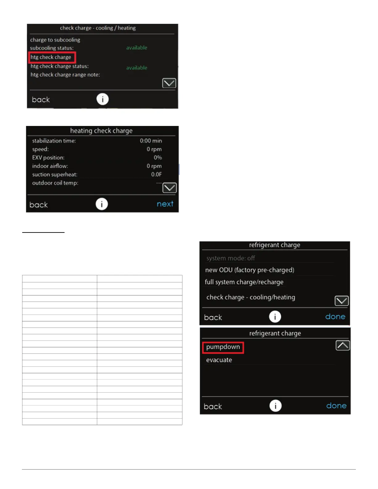
A240380
Fig. 23 – Heating Check Charge
A240382
Fig. 24 – Heating Check Charge Screen 1
Post Charging
Final charge should be recorded on the outdoor unit charging label with
permanent and legible writing. Total refrigerant charge is factory charge
plus any added charge. Verify the indoor space served by the indoor unit,
including spaces connected by ductwork, exceeds the minimum room
size as listed on the outdoor unit charging label. Refer to Table 5
Step 11 – Pump Down & Evacuation
Because this system has a VFD controlled compressor the conventional
procedure cannot be used to “pump down” and isolate the refrigerant
into the outdoor unit. The Infinity® System Control has provisions to
assist in performing this function.
1. Connect gauges to liquid and vapor or suction capillary service
ports to monitor operating pressures during and at completion of the
procedure.
2. In the “installation and service” menu of the Infinity® System
Control (see Fig. 13), go to “refrigerant charging” and then “pump
down” (see Fig. 14 and Fig. 25).
3. Pump down in COOL mode allows refrigerant to be isolated in
outdoor unit. Set desired time period. Default time period for the
procedure is 20 minutes. See Fig. 26.
4. Select Start on Infinity® System Control to begin the pump down
process. Unit will begin running in cooling mode after a brief delay
and a status screen will be displayed. See Fig. 27.
5. Close the liquid service valve.
6. The unit will run with the low pressure protection set to indicate
pump down is complete when the suction pressure drops below 20
psig. Compressor protections are still active to prevent damage to
the compressor or VFD (high pressure, high current, etc.).
7. Once system indicates pump down complete or failure to complete
shutdown, close vapor service valve.
8. A recovery system will be required to remove final quantity of
refrigerant from indoor coil and line set. Refer to Service Manual
for specific evacuation and purge steps required after recovering
refrigerant and before making any repairs to the indoor unit or
lineset.
9. Remove power from indoor and outdoor unit prior to servicing unit.
A240378
Fig. 25 – Pump Down and Evacuation Selection
Table 5 – Minimum Room Area Charging Table
Total System Charge (lbs.) Minimum Floor Area ft.
2
(m
2
)
4 61 (5.7)
5 76 (7.0)
6 91 (8.5)
7 106 (9.8)
8 122 (11.3)
9 137 (12.7)
10 152 (14.1)
11 167 (15.5)
12 182 (16.9)
13 198 (18.4)
14 213 (19.8)
15 228 (21.2)
16 243 (22.6)
17 258 (24.0)
18 274 (25.5)
19 289 (26.8)
20 304 (28.2)
21 319 (29.6)
22 335 (31.1)
23 350 (32.5)
24 365 (33.9)
25 380 (35.3)




 To Next Page