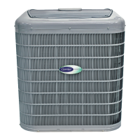
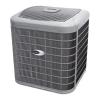
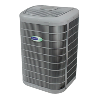
27VNA3 Infinity® Variable Speed Heat Pump: Installation Instructions
Manufacturer reserves the right to change, at any time, specifications and designs without notice and without obligations.
18
Input Filter Board
The input filter board connects the line voltage to the VFD. The input
filter board ensures the inherent electrical noise generated by VFD does
not affect other electronics in the household and contains fuses to protect
against excess input current.
Reactors
There are either 1 or 2 reactors per system depending on model. These
reactors are large inductors and must be connected to the VFD to
operate.
Variable Speed Compressor
This unit contains a high-side variable speed compressor that has a wide
operating range. Some models contain variable speed rotary
compressors while others contain variable speed scroll compressors. All
of the variable speed compressors operate on 3PH AC provided by the
VFD. This compressor can only be operated by the specific VFD
supplied with the unit.
Time Delays
The unit time delays include:
• Five minute time delay to start cooling or heating operation when
there is a call from the Infinity® System Control. To bypass this
feature, momentarily short and release Forced Defrost pins.
• Five minute compressor re-cycle delay on return from a brown-out
condition.
Heating Electronic Expansion Valve (EXV-H)
This unit uses an electronic expansion valve for refrigerant metering in
the heating mode. The control board drives the EXV to its proper
position based on the operating mode and conditions.
Vapor Injection Electronic Expansion Valve (EXV-VI)
Some models in this product family contain a secondary EXV for
controlling the vapor injection circuit. This circuit is comprised of a
brazed plate heat exchanger (BPHE), an EXV (EXV-VI) and
interconnecting tubing. The control of the vapor injection circuit allows
greater capacity and efficiency than when not operational.
Variable Speed Fan Motor
The fan motor included in this unit is a Brushless DC motor with an
integrated control module. The control module is supplied DC voltage
from the VFD. The speed command is provided from the VFD through a
0-5V signal. The commanded speed is determined by the PCM and is
communicated through Modbus to the VFD. The motor cannot be
connect to line voltage. Fan motor speed varies based on outdoor
ambient temperature, compressor, speed, and system demand. The fan
motor will not operate during defrost and may cycle off and on if
extremely low airflow is requested by the outdoor unit controls.
Pressure Equalization Valve (PEV)
The PEV is located at the discharge of the compressor and the inlet to the
accumulator. The purpose of the PEV is to prevent the compressor from
starting with a high pressure differential, which can cause compressor
damage. Occasionally the unit may experience a brief starting delay
while the PEV equalizes pressure before startup.
High Pressure Switch
This unit contains a high pressure switch to protect against high pressure
conditions. This switch must be closed for the VFD to be powered.
Outdoor Pressure Transducers
There are two pressure transducers installed on this unit. The pressure
transducers are connected to the P1 and P2 inputs on the PCM. Each
transducer may be connected to either PCM input. These transducers
have a range from 0 to 620 psig and are used for system protection,
control, and diagnostics.
Stator Heater Operation
This unit has an internal stator heating function. The compressor
windings will occasionally be energized during the OFF cycle to start the
stator heat operation, thus maintaining a sump temperature that is
essential for compressor reliability. The compressor will not run during
this process.
Infinity® Controlled Low Ambient Cooling
This unit is capable of low ambient cooling down to 0°F (-17.8°C) with
Low Ambient enabled on the Infinity® System Control. A low ambient
kit is not required.
The Infinity® System Control provides an automatic evaporator coil
freeze-protection algorithm that eliminates the need for an evaporator
freeze thermostat. The only accessories that may be required are wind
baffles in locations likely to experience cross winds in excess of 5 miles
an hour. This generally occurs only on roof and open-area applications.
Low ambient cooling must be enabled in the Infinity® System Control
setup. The outdoor unit fan will cycle on and off based on outdoor coil
temperature, outdoor air temperature, and suction pressure
measurements to keep the compressor running at the proper conditions.
Defrost
The Infinity® System Control offers 4 possible defrost interval times:
30, 60, 90 minutes or AUTO. The default is AUTO.
Defrost interval times: 30, 60, 90 minutes or AUTO are selected by the
Infinity® System Control (dip switches are not used.)
Auto mode will adjust the defrost interval dynamically based on
real-time frost accumulation and provide optimum system performance
when a fixed defrost interval time is chosen. In Auto mode, defrost will
begin when frost is detected on the coil. In non-frosting conditions, it is
possible to the unit to run for several days without initiating defrost.
The defrost process begins when the defrost interval time is reached
under frost-accumulating conditions. The defrost process ends when the
coil has sufficiently thawed and been allowed time to drain. Defrost may
also terminate as a result of a time limit - usually 15 minutes. If Defrost
is forced via the Forced Defrost input, defrost will be initiated regardless
of frost accumulation time or outdoor temperature. A forced defrost will
run at least 30 seconds, but may not run longer than 30 seconds if
ambient temperature is well above freezing.
NOTE: Compressor speed during defrost varies based on outdoor
conditions and unit model
WARNING
!
ELECTRICAL HAZARD - HIGH VOLTAGE
Failure to follow this warning could result in personal injury or death.
Electrical components may hold charge. DO NOT remove control box
cover for 2 minutes after power has been removed from unit.
PRIOR TO TOUCHING COMPONENTS:
Verify zero (0) voltage at VFD connections shown on control box
cover.
CAUTION
!
EQUIPMENT DAMAGE HAZARD
Failure to follow this caution may result in equipment damage.
Do not attempt to apply line voltage directly to the compressor. This
will destroy the compressor





 To Next Page