27VNA3 Infinity® Variable Speed Heat Pump: Installation Instructions
Manufacturer reserves the right to change, at any time, specifications and designs without notice and without obligations.
6
Install Liquid-Line Filter Drier - Indoor
Refer to Fig. 5 and install filter drier as follows: on 36 and 48 size
models
1. Braze 5-in. (127 mm) liquid tube to the indoor coil.
2. Wrap filter drier with damp cloth.
3. Braze filter drier to above 5-in. (127 mm) liquid tube.
4. Connect and braze liquid refrigerant tube to the filter drier.
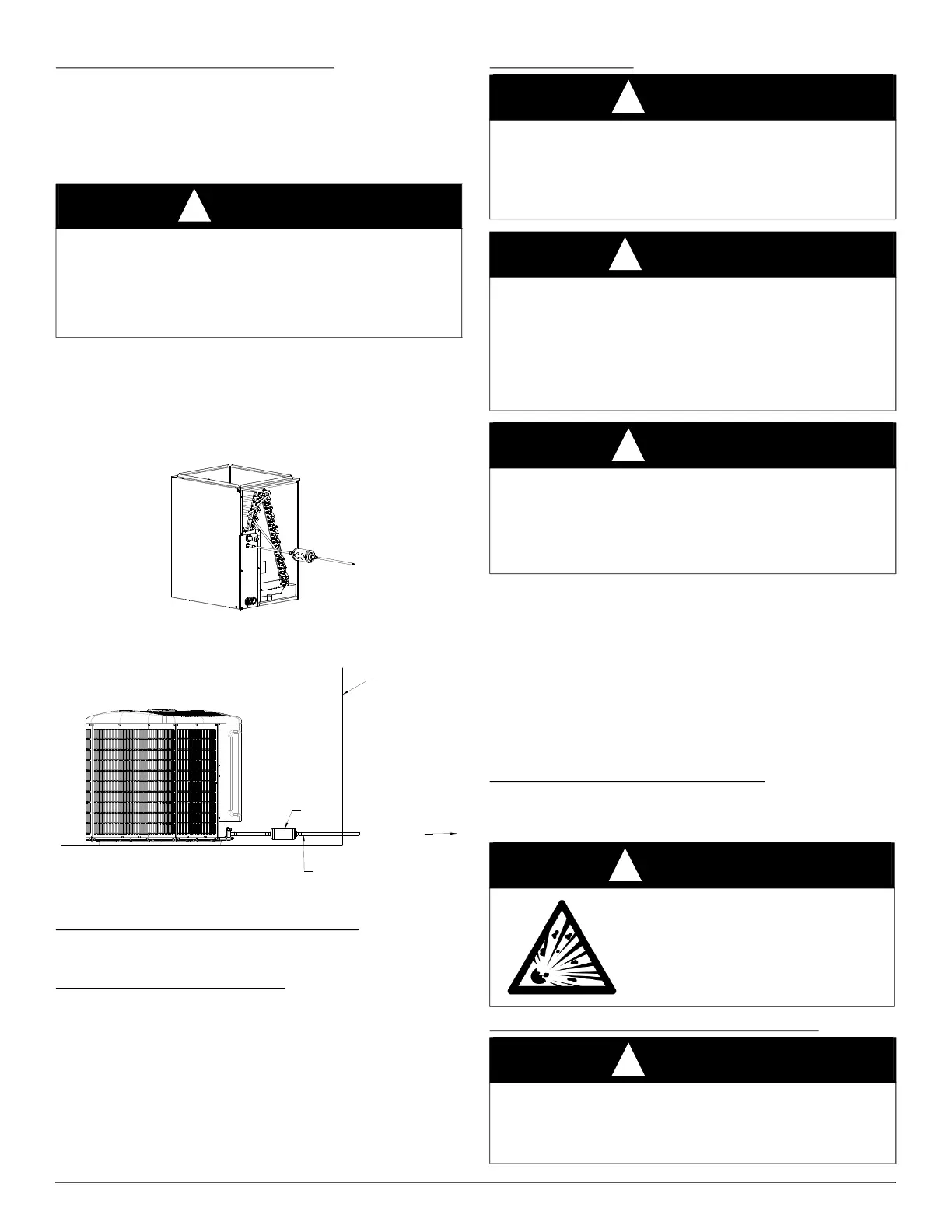
Refer to Fig. 6 and install filter drier as follows on 60 size models:
1. After wrapping the liquid service valve with a wet cloth braze 5-in.
(127 mm) liquid tube to the liquid service valve on outdoor unit.
2. Wrap filter drier with damp cloth.
3. Braze filter drier to above 5-in. (127 mm) liquid tube.
4. Connect and braze liquid refrigerant tube to the filter drier
A05227
Fig. 5 – Liquid-Line Filter Drier for 3 and 4 Ton Applications
A200059
Fig. 6 – Liquid-Line Filter Drier for 5 Ton Applications
Refrigerant Tubing Connection - Outdoor
Connect vapor tube to fitting on outdoor unit vapor service valves (see
Table 1).
No Installation of Adapter Tube
Although it is a heat pump this unit has a standard AC liquid service
valve. An EXV inside the unit serves as the heating expansion device.
Sweat Connections
Use refrigerant grade tubing. Service valves are closed from factory and
ready for brazing. Clean line set tube ends with emery cloth or steel
brush. Remove any grit or debris.
Insert line set tube ends into service valve tube stubs.
Apply heat absorbing paste or heat sink product between service valve
and joint. Wrap service valves with a heat sinking material such as a wet
cloth.
Braze joints using a Sil-Fos or Phos-copper alloy. Consult local code
requirements. Refrigerant tubing and indoor coil are now ready for leak
testing. This check should include all field and factory joints.
Pressure Test Tubing and Indoor Coil
Refrigerant tubes and indoor coil should be pressure tested with an inert
gas such as nitrogen. Pressurize the system with the inert gas to the Low
Side Test Pressure listed on the outdoor unit rating plate
Evacuate Refrigerant Tubing and Indoor Coil
CAUTION
!
UNIT DAMAGE HAZARD
Failure to follow this caution may result in unit damage or improper
operation.
Installation of filter drier in liquid line is required.
Filter drier must be wrapped in a heat-sinking material such as a wet
cloth while brazing
EXTERIOR
WALL
LIQUID LINE
FILTER DRIER
TO DWELLING
CAUTION
!
UNIT DAMAGE HAZARD
Failure to follow this caution may result in equipment damage or
improper operation.
• Use a brazing shield
• Wrap service valves with wet cloth or heat sink material.
WARNING
!
FIRE HAZARD
Failure to follow this warning could result in personal injury, death
and/or property damage.
Refrigerant and oil mixture could ignite and burn as it escapes and
contacts brazing torch. Make sure the refrigerant charge is properly
removed from both the high and low sides of the system before brazing
any component or lines.
CAUTION
!
BURN HAZARD
Failure to follow this caution may result in personal injury.
Components will be HOT after brazing. Wear appropriate personal
protective equipment and allow to cool before handling parts and
equipment.
WARNING
!
EXPLOSION HAZARD
Failure to follow this warning could result in
equipment damage or improper operation
Never exceed the test pressures listed on the
rating plate when pressure testing an outdoor
unit.
CAUTION
!
UNIT DAMAGE HAZARD
Failure to follow this caution may result in equipment damage or
improper operation.
Never use the system compressor as a vacuum pump.