25TPB7: Installation Instructions
Manufacturer reserves the right to change, at any time, specifications and designs without notice and without obligations.
3
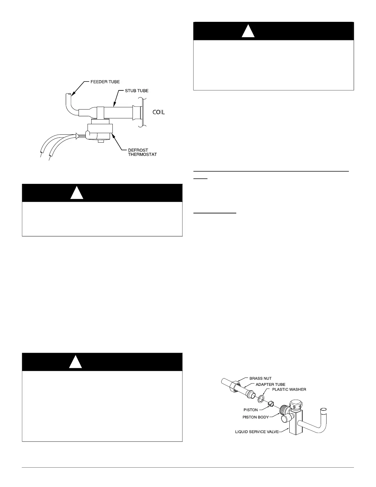
Check Defrost Thermostat
Check defrost thermostat to ensure it is properly located and securely
attached. There is a liquid header with a distributor and feeder tube
going into outdoor coil. At the end of the one of the feeder tubes, there is
a 3/8 in. O.D. stub tube approximately 2 in. long. (See Fig. 3.) The
defrost thermostat should be located on stub tube. Note that there is only
one stub tube used with liquid header, and on most units it is the bottom
circuit.
A97517
Fig. 3 – Defrost Thermostat Location
Elevate Unit
Elevate unit per local climate and code requirements to provide
clearance above estimated snowfall level and ensure adequate drainage
of unit.
In Long-Line Applications, Install Liquid-Line
Solenoid Valve (LSV)
For refrigerant piping arrangements with equivalent lengths greater than
80 ft. (24 m) and/or when elevation difference between indoor and
outdoor unit is greater than ±20 ft. (±6.1 m), follow all requirements of
the Residential Piping and Long-Line Guideline. If required by
Long-Line Guideline, install LSV kit, part no. KHALS0401LLS,
specifically designed for R-410A refrigerant heat pumps. LSV should be
installed within 2 ft. (0.6 m) of outdoor unit with flow arrow pointing
toward outdoor unit. Follow the Installation Instructions included with
accessory kit.
IMPORTANT: Flow arrow must point toward outdoor unit.
Make Piping Connections
Outdoor units may be connected to indoor section using accessory
tubing package or field-supplied refrigerant grade tubing of correct size
and condition. For tubing requirements beyond 80 ft (24 m), substantial
capacity and performance losses can occur. Following the
recommendations in the Residential Piping and Long Line Guideline
will reduce these losses. Refer to Table 1 for accessory requirements.
Refer to Table 2 for field tubing diameters.
There are no buried-line applications greater than 36 in. (914 mm)
If refrigerant tubes or indoor coil are exposed to atmosphere, they must
be evacuated to 500 microns to eliminate contamination and moisture in
the system.
Outdoor Unit Connected to Factory Approved Indoor
Unit:
Outdoor unit contains approximate system refrigerant charge for
operation with approved AHRI rated indoor unit when connected by 15ft
(4.6 m) of field–supplied or factory–accessory tubing, and factory
supplied filter drier. Check refrigerant charge for maximum efficiency.
Service Valves
Service valves are closed and plugged from the factory. Outdoor units
are shipped with a refrigerant charge sealed in the unit. Leave the service
valves closed until all other refrigerant system work is complete or the
charge will be lost. Leave the plugs in place until line set tubing is ready
to be inserted.
Heat pumps require a piston metering device in the liquid service valve
for proper heating operation. Piston is shipped in the piston body of the
liquid service valve, temporarily held in place with a plastic cap. Do not
remove the plastic cap until line set tubing is ready to be installed.
Refer to Fig. 4 and follow these steps for piston installation:
1. Remove plastic cap holding piston in piston body of liquid service
valve.
2. Check that piston size (stamped on side of piston) matches with
number listed on unit rating plate. Return piston to piston body of
liquid service valve (either direction).
3. Find plastic bag taped to unit containing copper adapter tube, brass
nut, and plastic washer.
4. Install plastic washer in the seat inside piston body.
5. Fit brass nut onto adapter tube and install tube onto liquid service
valve. Tighten nut finger tight, then wrench additional ½ turn only
[15-ft lbs (20 N-m)]. Over tightening may damage the plastic
washer and service valve’s piston body.
A14235
Fig. 4 – Liquid Service Valve with Heating Piston and Adapter Tube
CAUTION
!
UNIT OPERATION HAZARD
Failure to follow this caution may result in equipment damage or
improper operation.
Do not allow water and/or ice to build up in base pan.
WARNING
!
PERSONAL INJURY AND ENVIRONMENTAL
HAZARD
Failure to follow this warning could result in personal injury or death.
Relieve pressure and recover all refrigerant before system repair or
final unit disposal.
Use all service ports and open all flow-control devices, including
solenoid valves.
Federal regulations require that you do not vent refrigerant into the
atmosphere. Recover refrigerant during system repair or final unit
disposal
CAUTION
!
UNIT DAMAGE HAZARD
Failure to follow this caution may result in equipment damage or
improper operation.
If ANY refrigerant tubing is buried, provide a 6-in (152 mm). vertical
rise at service valve. Refrigerant tubing lengths up to 36-in (914 mm).
may be buried without further special consideration. Do not bury lines
longer than 36 in (914 mm).