9
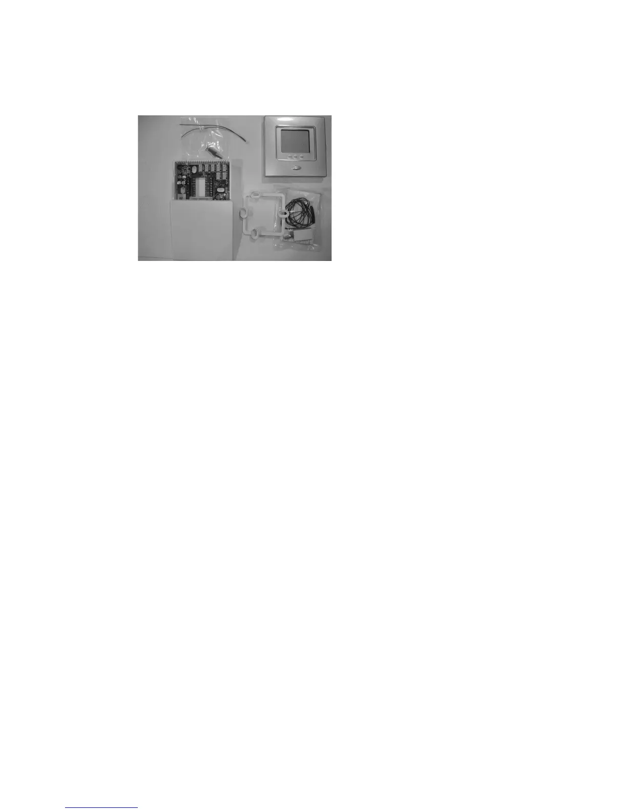
Carton contains the following components. See Fig. 3 for TP--PRH--A, --B or Fig. 4
f o r T P -- N R H -- A , -- B :
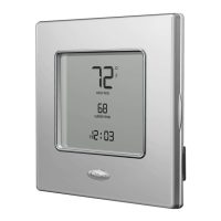
1. Display Module
2. Stand--off for Equipment Control Module
3. Outside Air Temperature Sensor, screws and pigtail
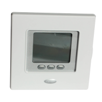
4. Equipment Control Module
A07686
Fig. 4 -- TP--NRH--A, --B Carton Contents
1. Display Module
2. Stand--off for Equipment Control Module
3. Outside Air Temperature Sensor, screws and pigtail
4. Equipment Control Module
Thermidistat Control Location
Thermidistat Control should be mounted:
S Approximately 5 ft (1.5m) from floor.