PF4MNB, PF4MNP: Installation Instructions
Manufacturer reserves the right to change, at any time, specifications and designs without notice and without obligations.
2
Installation
Check Equipment
Unpack unit and move to final location. Remove carton taking care not
to damage unit.
NOTE: If the door gasket is damaged or missing, the unit may not meet
the ASHRAE 193 standard for cabinet air leakage. Contact your supplier
and order kit #344994-751.
Inspect equipment for damage prior to installation. File claim with
shipping company if shipment is damaged or incomplete. Locate unit
rating plate which contains proper installation information. Check rating
plate to be sure unit matches job specifications.
Mount Unit
Unit can stand or lie on floor, or hang from ceiling or wall. Allow space
for wiring, piping, and servicing unit.
IMPORTANT: When unit is installed over a finished ceiling and/or
living area, building codes may require a field-supplied secondary
condensate pan to be installed under the entire unit. Some localities may
allow as an alternative, the running of a separate, secondary condensate
line. Consult local codes for additional restrictions or precautions.
NOTE: Nuisance sweating may occur if the unit is installed in a high
humidity environment with low airflow.
Upflow Installation
If return air is to be ducted through a floor, set unit on floor over opening
and use 1/8 to 1/4-in (3 to 6 mm) thick fireproof resilient gasket between
duct, unit, and floor.
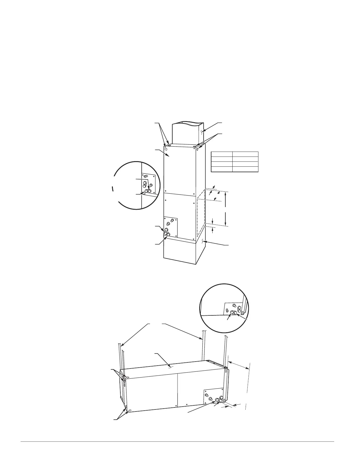
Side return is a field option on slope coil models. Cut opening per
dimensions (Fig. 1). A field-supplied bottom closure is required.
A07565
Fig. 1 – Slope Coil Unit in Upflow Application
A07566
Fig. 2 – Slope Coil in Horizontal Left Application (Factory Configuration)
A COIL
UNITS
POWER ENTRY
OPTIONS
LOW VOLT
ENTRY
OPTIONS
FIELD MODIFIED
SIDE RETURN
LOCATION FOR
SLOPE COIL
UNITS ONLY
FIELD SUPPLIED
RETURN PLENUM
UPFLOW/DOWNFLOW
SECONDARY DRAIN
UPFLOW/DOWNFLOW
PRIMARY DRAIN
UNIT
018, 024
025 - 030
A
12" (305 mm)
17" (432 mm)
A
1.5" (38 mm)
2.5"
(64 mm)
19" (483 mm)
FIELD SUPPLIED
SUPPLY DUCT
UPFLOW/DOWNFLOW
SECONDARY DRAIN
UPFLOW/DOWNFLOW
PRIMARY DRAIN
036 19" (483 mm)
018 - 048 21" (533 mm) FRONT SERVICE
060 - 060 24" (610mm) CLEARANCE
UNIT
FIELD
SUPPLIED
HANGING
STRAPS
LOW VOLT
ENTRY
OPTIONS
POWER
ENTRY OPTIONS
SECONDARY
DRAIN
018-048 21" (533 mm)
060-060 24" (610 mm)
FRONT SERVICE
CLEARANCE
(FULL FACE
OF UNIT)
SECONDARY
DRAIN
A-COIL
HORIZONTAL LEFT
PRIMARY
DRAIN
PRIMARY
DRAIN
1.75" (44 mm)
FILTER ACCESS
CLEARANCE

 Loading...