PF4MNB, PF4MNP: Installation Instructions
Manufacturer reserves the right to change, at any time, specifications and designs without notice and without obligations.
8
performance, BOTH primary and secondary drain lines should be
installed and include properly-sized condensate traps (Fig. 15 and
Fig. 17). Factory-approved condensate traps are available. It is
recommended that PVC fittings be used on the plastic condensate pan.
Finger-tighten plus 1-1/2 turns. Do not over-tighten. Use pipe dope.
NOTE: When connecting condensate drain lines, avoid blocking filter
access panel, thus preventing filter removal. After connection, prime
both primary and secondary condensate traps.
A03002
Fig. 15 – Recommended Condensate Trap
A03013
Fig. 16 – Insufficient Condensate Trap
NOTE: If unit is located in or above a living space where damage may
result from condensate overflow, a field-supplied, external condensate
pan should be installed underneath the entire unit, and a secondary
condensate line (with appropriate trap) should be run from the unit into
the pan. Any condensate in this external condensate pan should be
drained to a noticeable place. As an alternative to using an external
condensate pan, some localities may allow the use of a separate 3/4-in
(19 mm) condensate line (with appropriate trap) to a place where the
condensate will be noticeable. The owner of the structure must be
informed that when condensate flows from the secondary drain or
external condensate pan, the unit requires servicing or water damage will
occur.
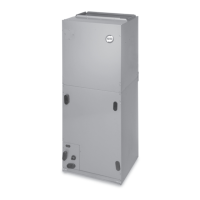
Install traps in the condensate lines as close to the coil as possible
(Fig. 17). Make sure that the outlet of each trap is below its connection
to the condensate pan to prevent condensate from overflowing the drain
pan. Prime all traps, test for leaks, and insulate traps if located above a
living area. Condensate drain lines should be pitched downward at a
minimum slope of 1-in (25 mm) for every 10-ft (3 m) of length. Consult
local codes for additional restrictions or precautions.
Accessories
Humidifier
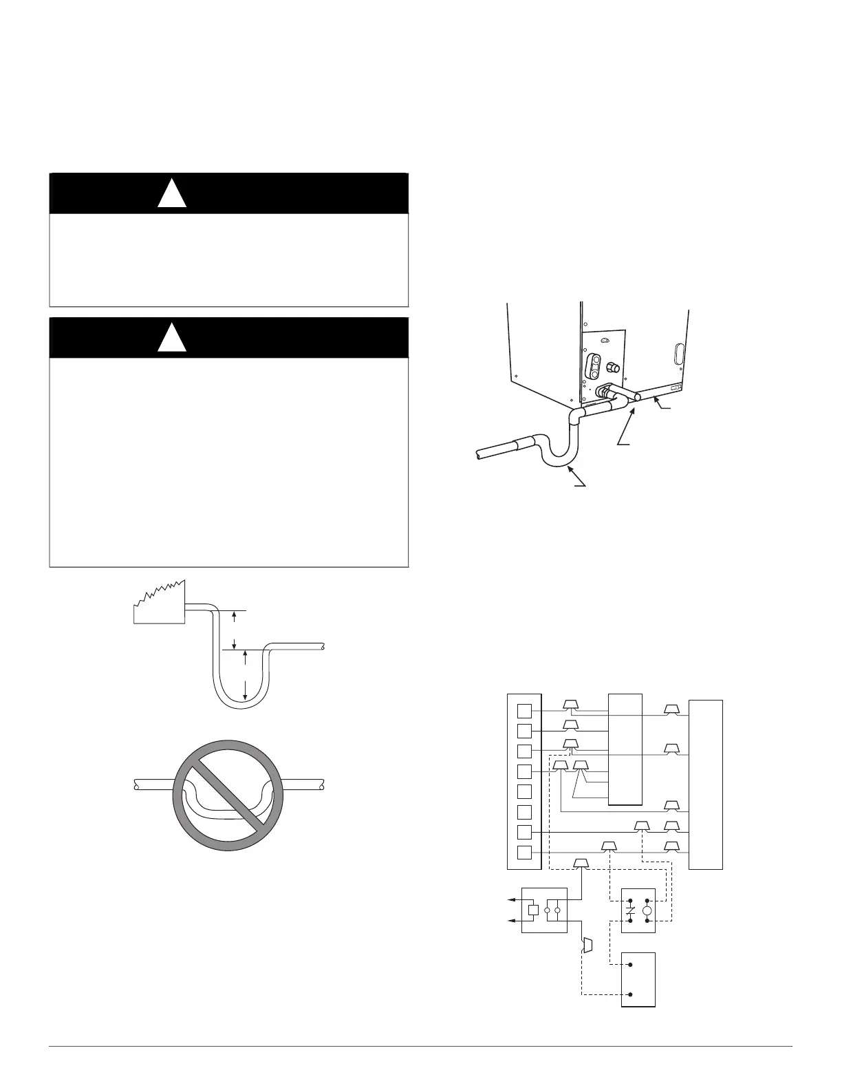
Connect humidifier and humidistat to fan coil unit as shown in Fig. 18
and Fig. 19. The cooling lockout relay is optional.
A03003
Fig. 17 – Condensate Drain
Sequence of Operation
Continuous Fan
Thermostat closes R to G. G energizes circuit to indoor blower motor.
When G is de-energized, there is a 90-second delay before relay opens.
A95294
Fig. 18 – Wiring Layout of Humidifier to Heat Pump
CAUTION
!
PRODUCT DAMAGE HAZARD
Failure to follow this caution may result in product or property damage.
Use only full size P-traps in the condensate line (Fig. 15). Shallow
running traps are inadequate and DO NOT allow proper condensate
drainage (Fig. 16).
CAUTION
!
UNIT OR PROPERTY DAMAGE HAZARD
Failure to follow this warning caution may result in product or property
damage.
The conversion of the fan coil to downflow requires special procedures
for the condensate drains on both A-coil and Slope-coil units. The
vertical drains have an overflow hole between the primary and
secondary drain holes. This hole is plugged for all applications except
downflow, and must be used for downflow. During conversion process,
remove plastic cap covering vertical drains only and discard. Remove
plug from overflow hole and discard. At completion of downflow
installation, caulk around vertical pan fitting to door joint to retain low
air leak performance of the unit.
2” MIN
(51 mm)
UNIT
2” MIN
(51 mm)
DO NOT USE SHALLOW RUNNING TRAPS!
FILTER
ACCESS
PANEL
SECONDARY DRAIN WITH
APPROPRIATE TRAP REQUIRED
(USE FACTORY KIT OR
FIELD-SUPPLIED TRAP)
PRIMARY TRAP REQUIRED
(USE FACTORY KIT OR
FIELD-SUPPLIED TRAP OF
SUFFICIENT DEPTH.
STANDARD P-TRAPS ARE
NOT SUFFICIENT. SEE
FIGURE OF RECOMMENDED
CONDENSATE TRAP)
R
G
C
E
L
O
Y
THERMOSTAT
R
R
C
O
Y
G
C
W
2
W
2
W
2
W
3
E
FAN COIL
(CONTROL)
HEAT PUMP
(CONTROL)
RED
GRY
BRN
WHT
WHT
BLU
VIO
HUMIDISTAT
RELAY
FAN HUMIDIFIER
115V
M

 Loading...