PF4MNB, PF4MNP: Installation Instructions
Manufacturer reserves the right to change, at any time, specifications and designs without notice and without obligations.
7
Ground Connections
NOTE: Use UL listed conduit and conduit connectors for connecting
supply wire(s) to unit to obtain proper grounding. Grounding may also
be accomplished by using grounding lugs provided in control box.
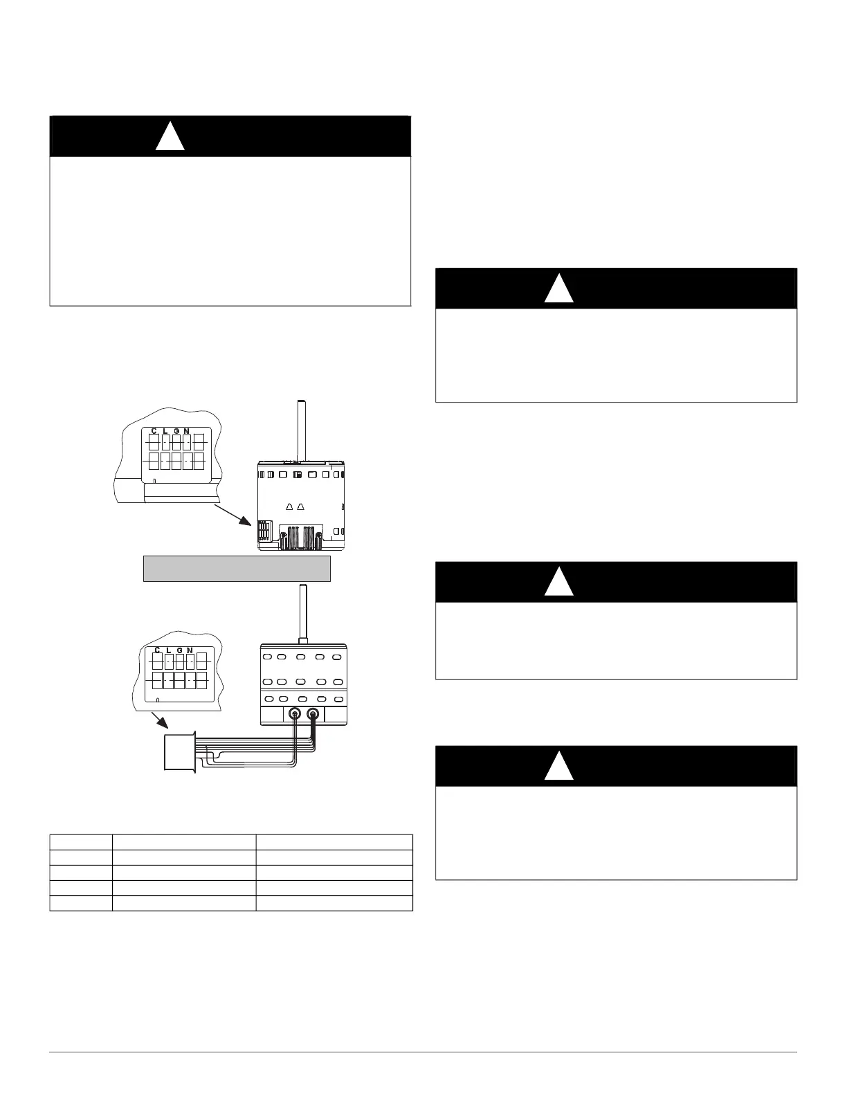
Minimum CFM and Motor Speed Selection
The fan speed selection is done at the motor connector. Units with or
without electric heaters require a minimum CFM. Refer to the unit
wiring label to ensure that the fan speed selected is not lower than the
minimum fan speed indicated.
A11048
Fig. 14 – Motor Speed Selection
† electric heat airflow is same CFM as Tap 3, except 0 sec off delay
‡ high static applications, see airflow tables for max airflow
To change motor speeds disconnect the BLUE fan lead from motor
connector terminal #2 (factory default position) and move to desired
speed-tap; 1, 2, 3, or 5.
Speed-taps 1, 2, and 3 have a 90-second blower off time delay
pre-programmed into the motor. Speed-tap 4 is used for electric heat
only (with 0 second blower time delay) and the WHITE wire should
remain on tap 4. Speed-tap 5 is used for high static applications, but has
a 0 second blower time delay pre-programmed into the motor. See
Airflow Performance tables for actual CFM. Also see Fig. 14 for motor
speed selection location.
NOTE: In low static applications, lower motor speed tap should be used
to reduce possibility of water being blown off coil.
Refrigerant Tubing Connection and
Evacuation
Use accessory tubing package or field-supplied tubing of refrigerant
grade. Suction tube must be insulated. Do not use damaged, dirty, or
contaminated tubing because it may plug refrigerant flow-control
device. ALWAYS evacuate the coil and field-supplied tubing to 500
microns before opening outdoor unit service valves.
Units have sweat suction and liquid tube connections. Make suction tube
connection first.
1. Cut tubing to correct length.
2. Insert tube into sweat connection on unit until it bottoms.
3. Braze connection using silver bearing or non-silver bearing brazing
materials. Do not use solder (materials which melt below 800°F /
427°C). Consult local code requirements.
4. Evacuate coil and tubing system to 500 microns using a deep
vacuum method.
Refrigerant Flow-Control Device
The PF4M units come equipped with a R-410A refrigerant TXV.
Always use outdoor units designed to match indoor fan coil applications.
Condensate Drains
To connect drains, the cap openings must be removed. Use a knife to
start the opening near the tab and using pliers, pull the tab to remove the
disk. Clean the edge of the opening if necessary and install the
condensate line. Finally caulk around the lines where they exit the fitting
to retain the low leak rating of the unit.
Units are equipped with primary and secondary 3/4-in. FPT drain
connections. For proper condensate line installations see Fig. 1 thru
Fig. 5. To prevent property damage and achieve optimum drainage
WARNING
!
ELECTRICAL SHOCK HAZARD
Failure to establish uninterrupted or unbroken ground could result in
personal injury and/or death.
According to NEC, NFPA 70, and local codes, the cabinet must have an
uninterrupted or unbroken ground to minimize personal injury if an
electrical fault should occur. The ground may consist of electrical wire
or metal conduit when installed in accordance with existing electrical
codes. If conduit connection uses reducing washers, a separate ground
wire must be used.
Table 1 – Fan Speed Selection
Tap 1
Low 90 sec off delay
Tap 2
Medium 90 sec off delay
Tap 3
High 90 sec off delay
Tap 4
Electric heat † 0 sec off delay
Tap 5
Max ‡ 0 sec off delay
1 2 3 4 5
Speed Taps may be located on motor,
or on plug close to motor.
CLGN
1 2 3 4 5
CAUTION
!
PRODUCT DAMAGE HAZARD
Failure to follow this caution may result in product or property damage.
A brazing shield MUST be used when tubing sets are being brazed to
the unit connections to prevent damage to the unit surface and
condensate pan fitting caps.
CAUTION
!
PRODUCT DAMAGE HAZARD
Failure to follow this caution may result in product or property damage.
Wrap a wet cloth around rear of fitting to prevent damage to TXV and
factory-made joints.
CAUTION
!
PRODUCT OPERATION HAZARD
Failure to follow this caution may result in improper product operation.
If using a TXV in conjunction with a single-phase reciprocating
compressor, a compressor start capacitor and relay are required.
Consult outdoor unit pre-sale literature for start assist kit part number.

 Loading...