Do you have a question about the Carrier PRO-DIALOG Plus 30GK Series and is the answer not in the manual?
Discusses potential hazards during installation, start-up, and servicing of equipment.
Details precautions and qualifications required to prevent electrocution from electrical components.
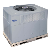
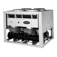
Introduces PRO-DIALOG Plus as a control system for units using reciprocating compressors.
Lists and defines abbreviations commonly used in the manual.
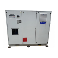
Overview of the control system components and their arrangement in the control cabinet.
Describes the different types of electronic boards used in the system and their functions.
Details various control components like EXV, head pressure controls, pumps, and sensors.
Outlines the available connections at the customer's terminal block for external interfaces.
Explains the structure and general operation of the local user interface.
Covers methods for starting, stopping, and selecting operating types for the unit.
Describes how to navigate and select items within the system menus.
Provides a visual representation of the overall menu hierarchy.
Details the hierarchical organization of various system parameters and functions.
Details the parameters displayed and accessible within the Information menu.
Lists and describes temperature-related parameters shown in the system.
Lists and describes pressure-related parameters shown in the system.
Explains how to display and modify setpoints for various operating parameters.
Lists and describes the status of unit digital and analogue inputs.
Details the status of unit outputs and how to perform manual tests.
Explains how to display and modify system configuration settings.
Describes how to display and reset active alarms.
Details how to view historical alarm codes and associated information.
Explains how to access and interpret runtime data for unit and compressor operation.
Summarizes unit control types, operating states, and parameters for starting/stopping.
Explains how heating/cooling mode is controlled based on operating type and contacts.
Details the control logic and operation for one or two evaporator water pumps.
Describes the control methods for the condenser pump on specific unit types.
Explains the function of the control interlock contact in preventing unit start-up.
Discusses the activation of the evaporator heater for ice protection.
Defines the control point and how it relates to active setpoint and reset.
Explains how demand limit restricts unit electricity consumption.
Details how compressors and unloaders are activated to maintain setpoint temperature.
Describes methods for configuring which circuit acts as the lead.
Explains the available sequences for loading circuits based on capacity demand.
Details how Electronic Expansion Valves (EXVs) control refrigerant flow.
Explains methods for controlling condenser fans based on setpoint or EXV position.
Details methods for controlling condenser water valves based on setpoint or EXV position.
Summarizes how active setpoints are selected based on operating mode and control types.
Explains how the function prevents high pressure breaks by shedding capacity.
Describes the pumping down cycle when compressors start or stop.
Details how two PRO-DIALOG Plus units can be linked as a master/slave assembly.
Explains how multiple units can be controlled by a System Manager module.
Outlines the change-over procedure from cooling to heat reclaim mode.
Introduces the fault tracing aid functions of the control system.
Explains how alarm LEDs and the Alarm menu indicate unit status.
Provides procedures for resetting active alarms manually or automatically.
Lists alarm codes, their descriptions, actions, and probable causes.
| Compressor Type | Scroll |
|---|---|
| Refrigerant | R410A |
| Energy Efficiency Ratio (EER) | Up to 3.2 |
| Power Supply | 400V/3Ph/50Hz |
| Control System | PRO-DIALOG Plus |