49
NOTES:
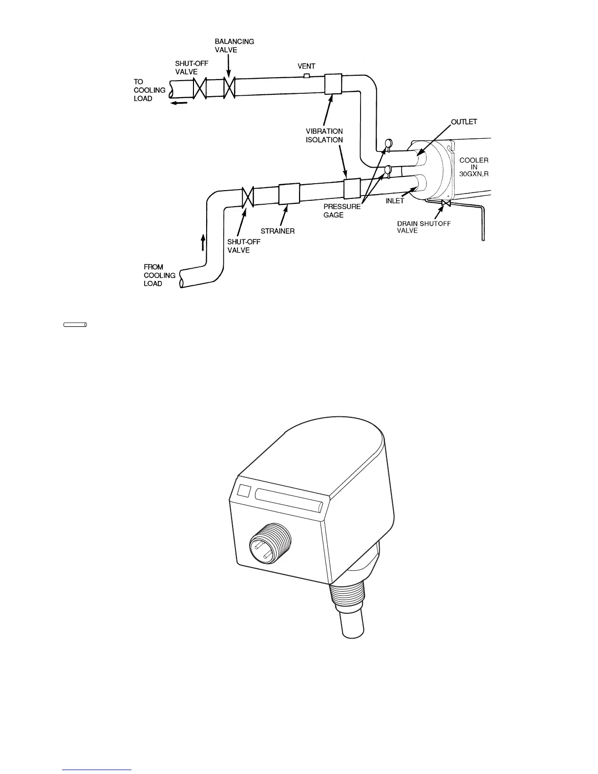
1. Piping shown is for general point-of-connection only and is not intended to
show details for specific installation. Certified dimensional diagrams are
available upon request. The 30GXN,R units should be installed using certified
drawings.
2. Refer to Carrier System Design Manual for details regarding piping techniques.
3. Piping, switches, valves, vent, gages, strainers, drain, and vibration isolation
are all field supplied.
Fig. 34 — Typical Cooler Piping
LEGEND
Field Piping
Fig. 35 — Thermal Flow Sensor