10
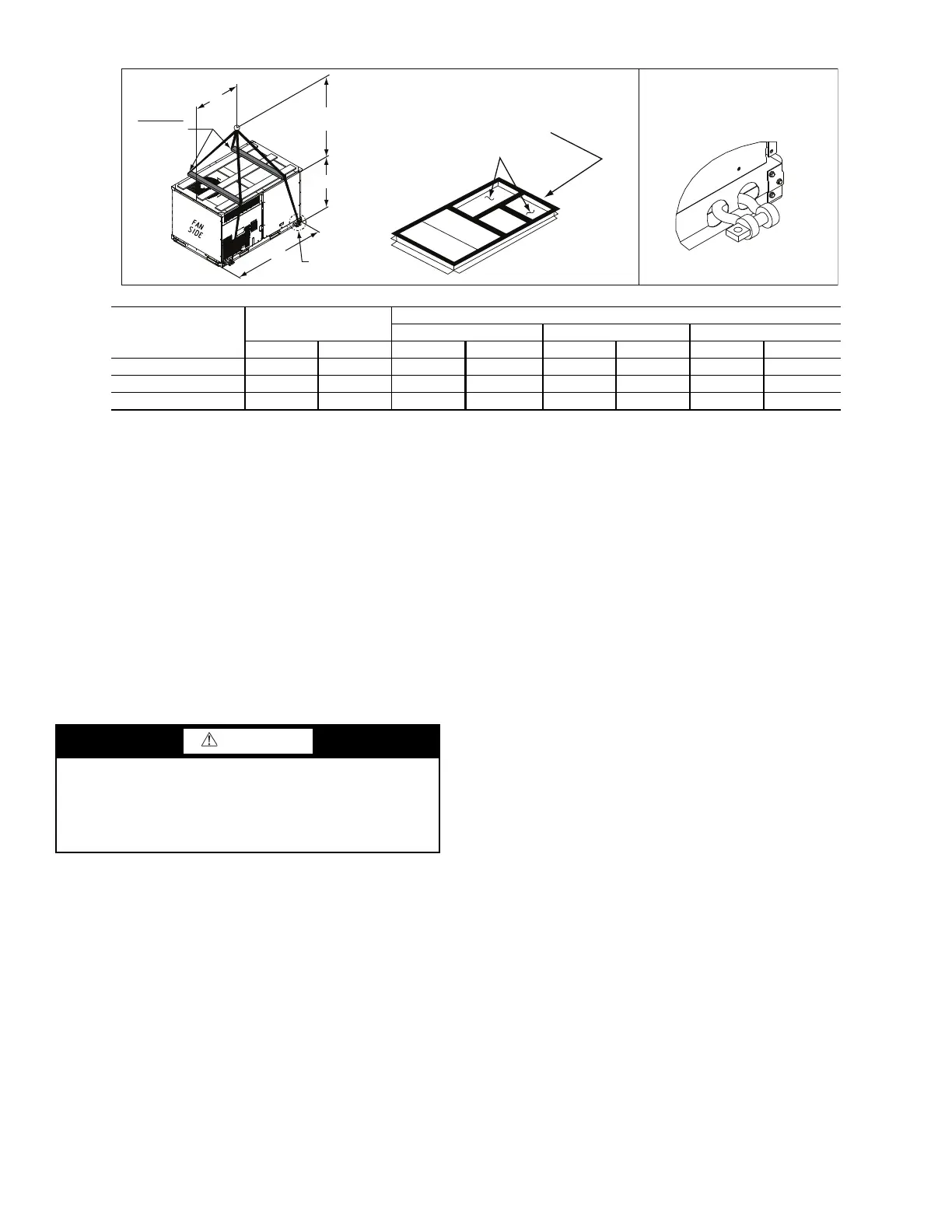
Fig. 6 — Rigging Details
POSITIONING ON CURB
Position unit on roof curb so that the following clearances
are maintained:
1
/
4
in. (6.4 mm) clearance between the roof
curb and the base rail inside the front and rear, 0.0 in. clear-
ance between the roof curb and the base rail inside on the
duct end of the unit. This will result in the distance between
the roof curb and the base rail inside on the condenser end of
the unit being approximately
1
/
4
in. (6.4 mm).
Although unit is weatherproof, guard against water from
higher level runoff and overhangs.
Flue vent discharge must have a minimum horizontal
clearance of 4 ft (1220 mm) from electric and gas meters, gas
regulators, and gas relief equipment. Minimum distance be-
tween unit and other electrically live parts is 48 inches
(1220 mm).
Flue gas can deteriorate building materials. Orient unit
such that flue gas will not affect building materials. Locate
mechanical draft system flue assembly at least 48 in.
(1220 mm) from an adjacent building or combustible
material.
NOTE: Installation of accessory flue discharge deflector kit will
reduce the minimum clearance to combustible material to 18 in.
(460 mm).
After unit is in position, remove rigging skids and ship-
ping materials.
Step 7 — Convert to Horizontal and Connect
Ductwork (When Required)
Unit is shipped in the vertical duct configuration. Unit with-
out factory-installed economizer or return-air smoke detector
option may be field-converted to horizontal ducted configura-
tion. To convert to horizontal configuration, remove screws
from side duct opening covers (see Fig. 7) and remove cov-
ers. Use the screws to install the covers on vertical duct open-
ings with the insulation-side down. The panels must be insert-
ed into the notches on the basepan to properly seal. The
notches are covered by the tape used to secure the insulation
to the basepan and are not easily seen. See Fig. 8 for position
of the notches in the basepan. Seals around duct openings
must be tight. Secure with screws as shown in Fig. 9. Cover
seams with foil duct tape.
Field-supplied flanges should be attached to horizontal duct
openings and all ductwork should be secured to the flanges.
Insulate and weatherproof all external ductwork, joints, and
roof or building openings with counter flashing and mastic in
accordance with applicable codes.
Do not cover or obscure visibility to the unit’s informative
data plate when insulating horizontal ductwork.
DETAIL "A"
PLACE ALL SEAL STRIP IN PLACE
BEFORE PLACING UNIT ON ROOF CURB.
DUCT END
SEE DETAIL "A"
"A"
(914-1371)
36"- 54"
"C"
"B"
SPREADER
BARS
REQUIRED
UNIT
MAX WEIGHT
DIMENSIONS
ABC
lb kg in. mm in. mm in. mm
48KC-A04 795 361 74.5 1890 39 990 33.5 850
48KC-A05 890 405 74.5 1890 39 990 33.5 850
48KC-A06 1020 464 74.5 1890 39 990 41.5 1055
NOTES:
1. SPREADER BARS ARE REQUIRED. Top damage will occur if spreader bars are not used.
2. Dimensions in () are in millimeters.
3. Hook rigging shackles through holes in base rail, as shown in Detail A. Holes in base rails are centered around the unit center of gravity. Use
wooden top to prevent rigging straps from damaging unit.
CAUTION
Failure to follow this caution may result in equipment dam-
age.
All panels must be in place when rigging. Unit is not
designed for handling by fork truck when panels or packag-
ing are removed.

 Loading...


