7
ROOF MOUNT
Check building codes for weight distribution require-
ments. Unit operating weights are shown in Table 2.
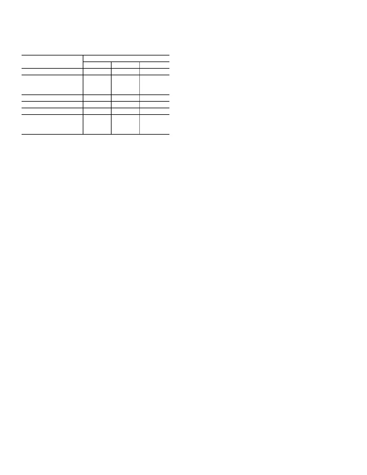
Table 2 — Operating Weights
Step 2 — Plan for Sequence of Unit Installation
The support method used for this unit will dictate different
sequences for the steps of unit installation. For example, on
curb-mounted units, some accessories must be installed on
the unit before the unit is placed on the curb. Review the fol-
lowing for recommended sequences for installation steps:
CURB-MOUNTED INSTALLATION
1. Install curb
2. Install field-fabricated ductwork inside curb
3. Install accessory thru-base service connection package
(affects curb and unit) (refer to accessory installation
instructions for details)
4. Prepare bottom condensate drain connection to suit
planned condensate line routing (refer to Install External
Condensate Trap and Line on page 15 for details)
5. Rig and place unit
6. Install outdoor air hood
7. Install flue hood
8. Install gas piping
9. Install condensate line trap and piping
10. Make electrical connections
11. Install other accessories
PAD-MOUNTED INSTALLATION
1. Prepare pad and unit supports
2. Check and tighten the bottom condensate drain connec-
tion plug
3. Rig and place unit
4. Convert unit to side duct connection arrangement
5. Install field-fabricated ductwork at unit duct openings
6. Install outdoor air hood
7. Install flue hood
8. Install gas piping
9. Install condensate line trap and piping
10. Make electrical connections
11. Install other accessories
FRAME-MOUNTED INSTALLATION
Frame-mounted applications generally follow the se-
quence for a curb installation. Adapt the sequence as required
to suit specific installation plan.
Step 3 — Inspect Unit
Inspect unit for transportation damage. File any claim with
transportation agency.
Confirm before installation of unit that voltage, amperage
and circuit protection requirements listed on unit data plate
agree with power supply provided.
On units with hinged panel option, check to be sure all
latches are snug and in closed position.
Locate the carton containing the outside air hood parts. Do
not remove carton until unit has been rigged and located in fi-
nal position.
Step 4 — Provide Unit Support
ROOF CURB MOUNT
Accessory roof curb details and dimensions are shown in
Fig. 4. Assemble and install accessory roof curb in accor-
dance with instructions shipped with the curb.
NOTE: The gasketing of the unit to the roof curb is critical
for a watertight seal. Install gasket supplied with the roof curb
as shown in Fig. 4. Improperly applied gasket can also result
in air leaks and poor unit performance.
Curb should be level. This is necessary for unit drain to
function properly. Unit leveling tolerances are shown in
Fig. 5. Refer to Accessory Roof Curb Installation Instructions
for additional information as required.
48KC--
UNIT LB (KG)
04 05 06
Base Unit 490 (222) 544 (246) 597 (270)
Economizer
Vertical 50 (23) 50 (23) 50 (23)
Horizontal 80 (36) 80 (36) 80 (36)
Humidi-MiZer
®
System 50 (23) 50 (23) 50 (23)
Cu Fins 25 (11) 43 (20) 56 (25)
Powered Outlet 35 (16) 35 (16) 35 (16)
Curb
14 in. (356 mm) 115 (52) 115 (52) 115 (52)
24 in. (610 mm) 197 (89) 197 (89) 197 (89)

 Loading...


