41
Step 14 — Adjust Factory-Installed Options
SMOKE DETECTORS
Smoke detector(s) will be connected at the Controls Connec-
tions Board, at terminals marked “Smoke Shutdown.” Cut
jumper JMP 3 when ready to energize unit.
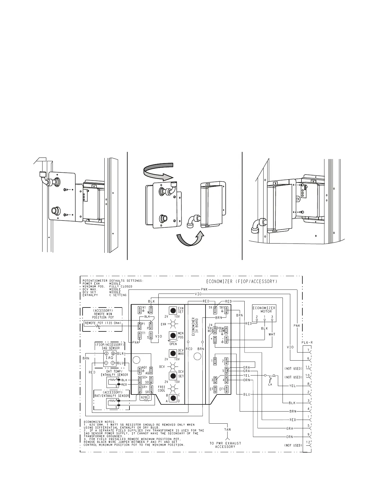
ECONOMI$ER IV OCCUPANCY SWITCH
See Fig. 58 for general EconoMi$er IV wiring. External oc-
cupancy control is managed through a connection on the
Controls Connections Board.
If external occupancy control is desired, connect a time
clock or remotely controlled switch (closed for Occupied,
open for Unoccupied sequence) at terminals marked OCCU-
PANCY. Cut jumper JMP 2 to complete the installation.
Step 15 — Install Accessories
Available accessories include:
• Curb
• Thru-base connection kit (must be installed before unit is
set on curb)
• LP conversion kit
• Flue discharge deflector
• Manual outside air damper
• Two-position motorized outside air damper
• EconoMi$er
®
IV (with control)
• EconoMi$er2 (without control/for external signal)
• Power Exhaust
• Differential dry-bulb sensor (EconoMi$er IV)
• Outdoor enthalpy sensor
• Differential enthalpy sensor
•CO
2
sensor
• DDC interface (PremierLink™ Controls)
• Louvered hail guard
• Motormaster
®
head pressure controls
• Phase monitor control
Refer to separate installation instructions for information
on installing these accessories.
Fig. 57 — Completing Installation of Return Air Smoke Sensor
Fig. 58 — EconoMi$er IV Wiring
STEP 1 STEP 2 STEP 3

 Loading...


