14
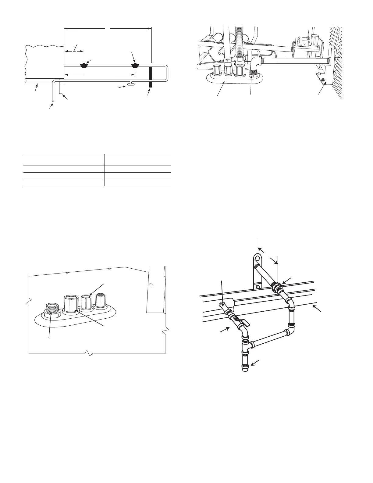
Fig. 17 — Gas Piping Guide
(with Accessory Thru-the-Curb Service
Connections)
FACTORY-OPTION THRU-BASE CONNECTIONS (GAS
CONNECTIONS)
This service connection kit consists of a
1
/
2
-in. NPT gas
adapter fitting (brass), a
1
/
2
-in. electrical bulkhead connector
and a
3
/
4
-in. electrical bulkhead connector, all factory-in-
stalled in the embossed (raised) section of the unit basepan in
the condenser section. See Fig. 18.
Fig. 18 — Thru-Base Gas Connection Fittings
The thru-base gas connector has male and female threads.
The male threads protrude above the basepan of the unit; the
female threads protrude below the basepan.
Check tightness of connector lock nuts before connecting
gas piping.
Install a
1
/
2
-in. NPT street elbow on the thru-base gas fit-
ting. Attach a
1
/
2
-in. pipe nipple with minimum length of
16-in. (406 mm) (field-supplied) to the street elbow and ex-
tend it through the access panel at the gas support bracket.
See Fig. 19.
Fig. 19 — Gas Line Piping for 3 to 5 Ton Units Only
Other hardware required to complete the installation of the
gas supply line includes a manual shutoff valve, a sediment
trap (drip leg) and a ground-joint union. A pressure regulator
valve may also be required (to convert gas pressure from
pounds to inches of pressure). The manual shutoff valve must
be located within 6 ft (1.83 m) of the unit. The union, located
in the final leg entering the unit, must be located at least 9 in.
(230 mm) away from the access panel to permit the panel to
be removed for service. If a regulator valve is installed, it
must be located a minimum of 4 ft (1220 mm) away from the
unit’s flue outlet. Some municipal codes require that the man-
ual shutoff valve be located upstream of the sediment trap.
See Fig. 20 and 21 for typical piping arrangements for gas
piping that has been routed through the sidewall of the curb.
See Fig. 20 for typical piping arrangement when thru-base is
used. Ensure that all piping does not block access to the unit’s
main control box or limit the required working space in front
of the control box.
Fig. 20 — Gas Piping, Typical Curb Sidewall Piping
(Example 1)
X
BASE UNIT
BASE RAIL
ROOF
CURB
9” MINIMUM CLEARANCE
FOR PANEL REMOVAL
MANUAL GAS
SHUTOFF VALVE
*
GAS
REGULATOR
*
48” MINIMUM
DRIP LEG
PER NFGC
*
FIELD-FABRICATED
SUPPORT
*
FROM
GAS
METER
LEGEND *Field supplied.
NOTE: Follow all local codes.
NFGC —
National Fuel Gas
Code
STEEL PIPE NOMINAL
DIAMETERS (IN.)
SPACING OF SUPPORTS
X DIMENSION (FT.)
1
/
2
6
3
/
4
or 1 8
1-
1
/
4
or larger 10
LOW VOLTAGE
CONDUIT
CONNECTOR
HIGH VOLTAGE
CONDUIT
CONNECTOR
BRASS FITTING FOR 3 TO 6 TON UNITS.
EMBOSSMENT
BRASS FITTING
FOR 3-6 TON UNITS
SUPPORT
BRACKET
9” (229mm) MIN
UNION
SHUT OFF
VALVE
DRIP
LEG
THRU-CURB ADAPTER
UNIT BASE R

 Loading...


