16
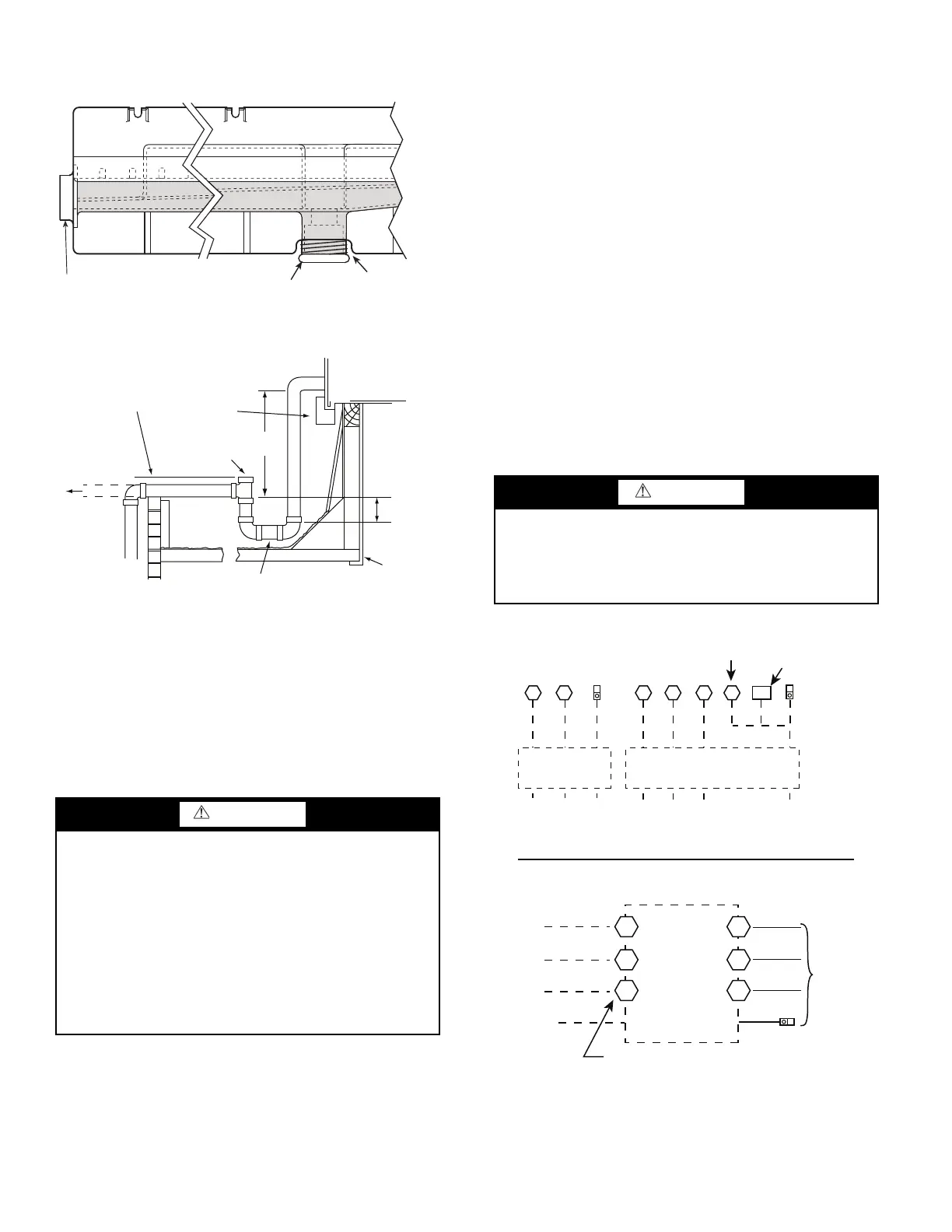
The piping for the condensate drain and external trap can
be completed after the unit is in place. See Fig. 25.
Fig. 24 — Condensate Drain Pan (Side View)
Fig. 25 — Condensate Drain Pan Piping Details
All units must have an external trap for condensate drain-
age. Install a trap at least 4 in. (102 mm) deep and protect
against freeze-up. If drain line is installed downstream from
the external trap, pitch the line away from the unit at 1 in. per
10 ft (25 mm per 3 m) of run. Do not use a pipe size smaller
than the unit connection (
3
/
4
in.).
Step 13 — Make Electrical Connections
NOTE: Field-supplied wiring shall conform with the limitations
of minimum 63°F (33°C) rise.
FIELD POWER SUPPLY
If equipped with optional Powered Convenience Outlet,
the power source leads to the convenience outlet’s
transformer primary are not factory connected. Installer must
connect these leads according to required operation of the
convenience outlet. If an always-energized convenience
outlet operation is desired, connect the source leads to the line
side of the unit-mounted disconnect. (Check with local codes
to ensure this method is acceptable in your area.) If a de-
energize via unit disconnect switch operation of the
convenience outlet is desired, connect the source leads to the
load side of the unit disconnect. On a unit without a unit-
mounted disconnect, connect the source leads to compressor
contactor C and indoor fan contactor IFC pressure lugs with
unit field power leads. See Convenience Outlets on page 18
for power transformer connections.
The field power wires are connected to the unit at line-side
pressure lugs on compressor contactor C and indoor fan
contactor IFC (see wiring diagram label for control box
component arrangement) or at factory-installed option non-
fused disconnect switch or HACR. Maximum wire size is
#2ga AWG (copper only) per pole on contactors and #2ga
AWG (copper only) per pole on optional disconnect or
HACR. See Fig. 26 and unit label diagram for field power
wiring connections.
NOTE: Unit may be equipped with short test leads (pigtails) on
the field line connection points on contactor C or optional dis-
connect switch. These leads are for factory-run test purposes on-
ly; remove and discard before connecting field power wires to
unit connection points. Make field power connections directly to
line connection pressure lugs only.
Fig. 26 — Power Wiring Connections
WARNING
Failure to follow this warning could result in personal injury
or death.
Do not use gas piping as an electrical ground. Unit cab-
inet must have an uninterrupted, unbroken electrical
ground to minimize the possibility of personal injury if an
electrical fault should occur. This ground may consist of
electrical wire connected to unit ground lug in control
compartment, or conduit approved for electrical ground
when installed in accordance with NEC (National Electri-
cal Code); ANSI/NFPA 70, latest edition (in Canada, Ca-
nadian Electrical Code CSA [Canadian Standards Associ-
ation] C22.1), and local electrical codes.
DRAIN
(FACTORY-INSTALLED)
PLUG
CONDENSATE PAN (SIDE VIEW)
STANDARD
SIDE DRAIN
ALTERNATE
BOTTOM DRAIN
NOTE: Trap should be deep enough to offset maximum unit static
difference. A 4-in. (102 mm) trap is recommended.
MINIMUM PITCH
1˝ (25 mm) PER
10´ (3 m) OF LINE
BASE RAIL
OPEN
VENT
TO ROOF
DRAIN
DRAIN PLUG
ROOF
CURB
SEE NOTE
3˝ (76 mm)
MIN
CAUTION
Failure to follow this caution could result in fire, intermittent
operation, or unsatisfactory performance.
Do not connect aluminum wire between disconnect
switch and air conditioning unit. Use only copper wire.
See Fig. 27.
C
11 23
Disconnect
per
NEC
208/230-1-60
or
Disconnect
per
NEC
11 13 13 23
L1 L2 L3
TB
CIFC
Direct Drive IFM
208/230-3-60
460-3-60
575-3-60
Units Without Disconnect or HACR Option
Units With Disconnect or HACR Option
L1
L2
L3
2
4
6
1
5
Optional
Disconnect
Switch
Disconnect factory test leads; discard.
Factory
Wiring
1-ph Belt Drive IFM
3
Equip
GR Lug
Ground
(GR)
Ground
(GR)
Equip
GR Lug
Equip GR Lug
Ground
(GR)
3 Phase Only 3 Phase Only

 Loading...


