10
Installation manual
Table.4-5
Remark
Factory default
Customization needed
Static pressure
0Pa
0~20Pa
Above 20Pa
Remove the wire mesh and connect them
to the wind duct (less than 3 meters).
Fig.4-27
Fig.4-28
Fig.4-29
Fig.4-30
Fig.4-31
Fig.4-32
Fig.4-33
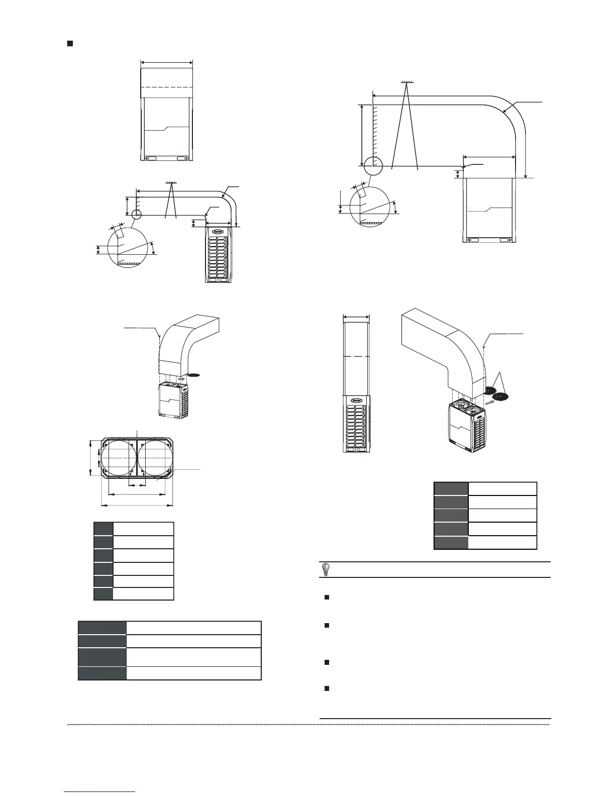
Air outlet louver dimension (optional)
Example A
Example B
14~22HP Installation illustration
Radius
Radius
Radius
Radius
Support
Support
Remove the two
iron filters first
Remove the
two iron filters first
12 x ST3.9 self-threading screws
12 x ST3.9 self-threading screws
630
A
C
D
B
90
100
θ
1290
E
B
A
630
C
90
100
θ
1310
1290
D
1290
1020
300
320
12×φ3.3
630
A≥300
B≥250
630≤D≤660
C≤3000
A
B
C
D
E=A+630
E
θ
≤15°
θ
NOTE
Before installing the air deflector, remove the mesh enclosure to
prevent air supply blockages.
Mounting the shutter on the unit limits the air volume, cooling
(heating) capacity, and efficiency depending on the shutter
angle. Do not mount the shutter or keep it angled to under 15°.
Only one bending site is allowed in the air duct (see as above
figure) or the unit may not function normally.
Install the flexible connector between the unit and the air pipe
to avoid noise from vibrations
A≥300
B≥250
C≤3000
A
B
C
D=A+1290
D
θ
≤15°
θ
 Loading...