24
Installation manual
Fig.7-1
Fully turn on the air pipe stop valve, liquid pipe stop valve, oil
balance valve, and air balance valve. If the above valves are
not turned on fully, the unit will be damaged.
Check whether the power phase sequence of outdoor unit is
correct.
All dial switches for indoor and outdoor units are set according
to the Technical Requirements of the Product.
7.3 Fill the name of connected system
To clearly identify the connected systems between two or
more indoor units and the outdoor unit, select names for
every system, and record them on the nameplate on the
outdoor electric control box cover.
Model(indoor unit)
Room Name e.g., indoor
unit (A) of the first system
on second floor is recorded
as:-2F-1A
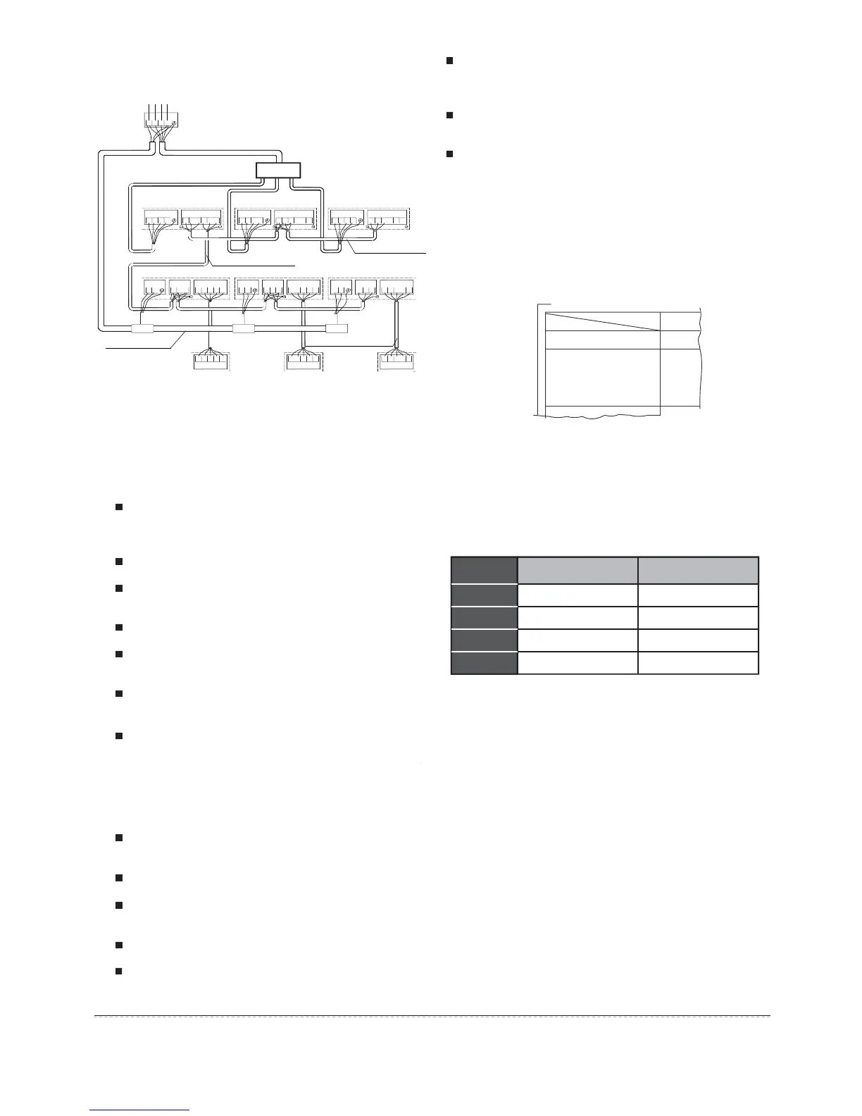
Outdoor unit(master unit)
Outdoor unit(slave unit) Outdoor unit(slave unit)
Signal wire between indoor/outdoor units
Signal wire between outdoor units
Indoor unit
Indoor unit
Indoor unit
Signal wire between indoor units
Signal wire between indoor unit and wire controller
B C N A P Q E E H2 H1
L N E Q P
B C N A P Q E E H2 H1 B C N A P Q E E H2 H1
C D E B A L N E C D E B A L N E C D E B A Q P Q P
B C N A
C D E B A C D E B A C D E B A
Branch Box
Branch Box
L2
L3
N
L1
Power(380-415V 3N
~
50Hz/60Hz)
Branch Box Branch Box
Wire controller Wire controller Wire controller
Fig.6-11
Check that the refrigeration pipe line and communication
wire between the indoor and outdoor units are connected
to the same refrigeration system or faults will occur.
Power voltage is within ±10% of the rated voltage.
Check that the power wire and control wire are correctly
connected.
Check that the wire controller is properly connected.
Before powering on, confirm there is no short circuit on
each line.
Check whether all units have passed a nitrogen pressure
test for 24 hours with R410A: 40 kg/cm
2
.
Confirm whether system debugging has been carried out
for vacuum drying and packed with refrigeration as
required.
Calculating the additional refrigerant quantity for each set
of units according to the actual length of the liquid pipe.
Keep the required refrigerant ready.
Keep the system plan, system piping diagram, and control
wiring diagram handy.
Record the setting address code on the system plan.
Turn on the power switches for outdoor units in advance,
and keep them connected for at least 12 hours, so that the
heater heats up the refrigerant oil in compressor.
6.8 Example for power wire connection
7.1 Inspection and confirmation before
commissioning
7.2 Preparation before debugging
7. TRIAL RUN
Table.7-1
Factory charge / kg tonnes CO2 equivalent
Model
8,10HP
12HP
9.00
11.00
22.97
14,16,18HP
13.00
27.14
20,22HP 16.00
33.41
18.79
This product has the fluorinated gas which is listed in kyoto
protocol it is forbidden to release to air.
Refrigerant type: R410A,volume of GWP: 2088,
GWP=Global Warming Potential
7.4 Important information for the used
refrigerant
Attention:
Frequency of Refrigerant Leak Checks.
1) For equipment that contains fluorinated greenhouse gases in
quantities of 5 tonnes of CO
2 equivalent or more,but of less
than 50 tonnes of CO
2 equipment,at least every 12 monthes,or
where a leakage detection system is installed, at least every 24
monthes.
2) For equipment that contains fluorinated greenhouse gases in
quantities of 50 tonnes of CO2 equivalent or more,but of less
than 500 tonnes of CO2 equipment,at least every six monthes,
or where a leakage detection system is installed, at least every
12 monthes.
3) For equipment that contains fluorinated greenhouse gases in
quantities of 500 tonnes of CO2 equivalent or more,at least
every three monthes ,or where a leakage detection system is
installed, at least every six monthes.
4) Non-hermetically sealed equipment charged with fluorinated
greenhouse gases shall only be sold to the end user where
evidence is provide that the installation is to be carried out by
an undertaking certified person.
5) Only certificated person is allowed to do installation, operation
and maintenance.
 Loading...