22
Installation manual
90
64
70
95
70
95
70
95
90
110
90
110
90
110
90
110
90
110
44
46
48
50
52
54
56
58
60
62
64
Total HP <20m <50m
8 10 16
10 16
10 16
16 25
16 25
16 25
16 25
16 25
25 35
25 35
25 35
35 50
35 50
35 50
35 50
35 50
35 50
50 70
50 70
50 70
50 70
10
12
14
16
18
20
22
24
26
28
30
32
34
36
38
40
42
Table.6-4
Select the capacity of manual switch and fuse of the branch
box.
See the following table. When there are no power facilities, it
depends on the outdoor unit it connects to.
See table.6-4 below. When there is power, it depends on total
horsepower.
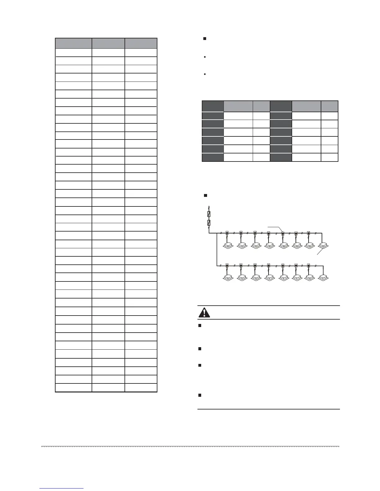
Indoor power supply
Indoor power
Leakage protector
Manual switch
Branch box
Indoor unit
Fig.6-7
Set the refrigerant piping system, signal wires between
indoor-indoor unit, and those between the outdoor-outdoor
unit into one system.
Unify the power supply to all indoor units in the same
system.
Do not put the signal wire and power wire in the same wire
tube; keep some distance between the two tubes. (Current
capacity of the power supply: less than 10A--300mm, less
than 50A--500mm.)
Set the address of the outdoor unit in case there are parallel
multi-outdoor units.
CAUTION
1
9
2
10
3
11
4
12
5
13
6
14
7
15
8
16
Table.6-5
Total horsepower, capacity of manual switch and fuse
Total (HP)
Manual switch (A)
Fuse(A)
8~12
14
18
20~22
24~28
30~34
32
40
50
63
80
100
25
35
16
40
35
40
50
70
80
Total (HP)
Manual switch (A)
Fuse(A)
36~40
42~44
125
125
100
100
46~50
52~60
62~88
150
200
250
125
150
200
90
110
66
90
110
68
90
110
70
90 110 72
90 110 76
90 110 74
90 110 78
90 110 80
90 110 82
90 110 84
90 110 86
90
110
88
 Loading...