Do you have a question about the CAS NT-500 Series and is the answer not in the manual?
Essential safety guidelines and warnings for operating the weighing indicator.
Important notes on maintaining accurate readings and preventing damage.
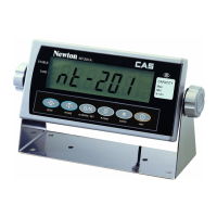
Key characteristics and capabilities of the weighing indicator.
Core operational capabilities and functionalities of the device.
Details on analog input, A/D conversion, and related parameters.
Specifications related to the digital display, calibration, and indicators.
Overall product specifications including power, size, and environment.
Available optional interfaces and outputs for the indicator.
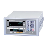
Explanation of indicator lamps and the NT-505A sub display.
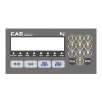
Diagrams of the keyboard layout for NT-501A, NT-502A, and NT-505A.
Detailed descriptions of individual keys and their functions on the front panel.
Instructions for connecting the load cell to the indicator.
Table showing load cell output voltage and recommended resolution.
Connecting external input/output devices via the rear panel.
Details on AC power connection and internal load cell output switches.
Wiring and connection guide for serial communication with a PC.
Instructions for connecting a CD-Series sub-display.
Settings for baud rate, data bits, parity, and data format.
List of commands and their functions for serial communication.
Steps to activate the test mode on the indicator.
Explanation of keys used for navigation and value changes in test mode.
Overview of the different diagnostic tests available.
Key code mapping and details for VF Display and Load Cell tests.
Instructions for Serial Interface and Printer tests.
Details for SRAM, I/O, BCD, and Analog output tests.
Procedure for accessing the calibration mode.
Keys used for calibration and the available calibration menus (CAL1-CAL7).
Setting the maximum weight capacity of the scale.
Configuring the minimum division for the scale's resolution.
Defining the weight for span calibration.
Performing the zero point calibration of the scale.
Executing the span calibration with a known weight.
Checking the accuracy and proper completion of the calibration.
Calibrating with a weight constant after selecting a national code.
Procedure to access the set mode for parameter configuration.
Keys used for navigation and value adjustment within set mode.
Overview of the configurable parameters and their ranges.
Configuration options for serial communication parameters.
Settings related to printer selection, format, and output.
Configuration for external input/output relays and signals.
Settings for optional interfaces like BCD and Analog output.
Configuration for date, time, display speed, and digital filter.
Settings for stable condition, automatic zero, and weight backup.
Configuration for hold type, average time, filter, and key conditions.
Settings for load cell type and 8/9 key functionality.
Configuring the baud rate for serial communication.
Setting data bits, stop bits, and parity for serial data.
Configuring data transmission modes and conditions.
Assigning a unique device ID for identification.
Selecting the format for serial data transmission.
Choosing the type of printer to be used with the indicator.
Selecting from various print formats for outputting data.
Configuring manual or automatic printing behavior.
Resetting weighing numbers and accumulated data.
Entering custom messages or information for printing.
Configuring the number of line feeds for paper output.
Configuring the relay modes (Limit, Checker, Packer).
Setting the start delay time for finish relays.
Setting the end delay time for finish relays.
Configuring the range for zero relay activation.
Setting the input range for key inputs.
Selecting options like BCD output or Analog output.
Setting the output current at zero weight.
Setting the output current at maximum capacity.
Choosing between Net or Gross data for analog output.
Defining the maximum analog output value at specific weights.
Setting the logic (Positive/Negative) for BCD output.
Steps for performing zero compensation on the scale.
Switching and displaying between net and gross weight.
Procedure to adjust the digital filter for weight display.
Steps for saving identification codes for weighed items.
How to set the upper limit value for weighing.
How to set the upper fall limit value for weighing.
Procedure for clearing saved ID data.
Instructions for printing the subtotal of weighed items.
Instructions for printing the overall grand total.
Details and connection for the RS-422 serial interface option.
Description and functionality of the BCD output interface.
Specifications and setup for analog output (0-24mA, 0-10V).
Procedure for sealing the rear panel connections.
Procedure for sealing the load cell connector.
Common error codes and solutions during weighing operations.
Error codes and troubleshooting steps for calibration mode.
| Brand | CAS |
|---|---|
| Model | NT-500 Series |
| Category | Accessories |
| Language | English |