SECTION 2 - CONTROLS, INSTRUMENTS AND OPERATION
2ï14
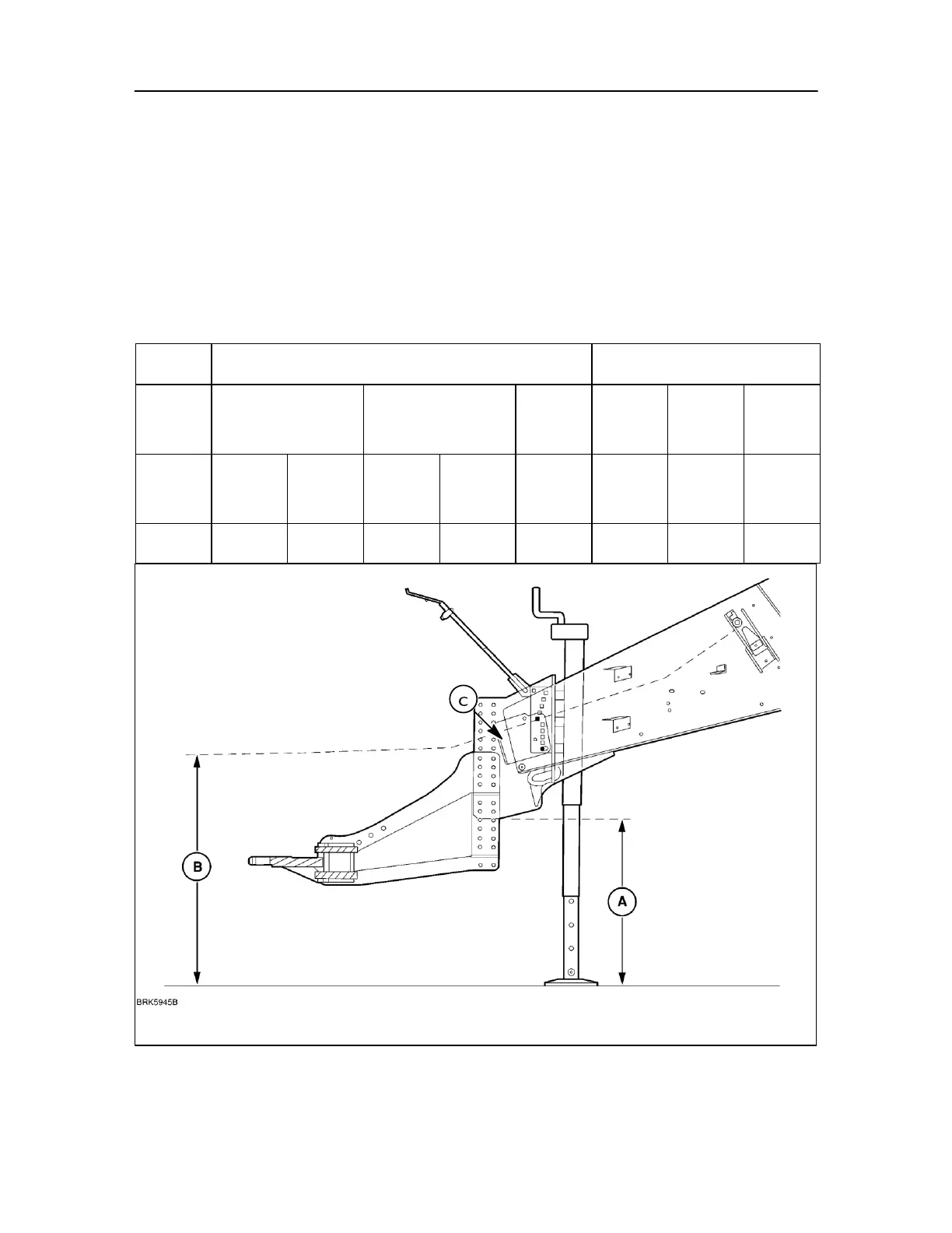
PTO Shaft alignment
Shown below are tables of dimensions, for the positioning of the PTO shaft.
This is with the baler pick-up on the ground to achieve optimum position for the middle bearing and PTO
alignment.
IMPORTANT: If you experience any difficulty applying this set up to your tractor refer to your dealer for assistance.
Especially when you want to set up the configuration in position 6.
Baler adjustment
1. First action is to set is hitch height by adjusting the jack according to dimensions in the following table
andillustration (dimension A). Attach the hitch.
Baler hitch height (A)