SECTION 2 - CONTROLS, INSTRUMENTS AND OPERATION
2ï19
PTO Ring
Prior to fitting the PTO shaft this drive line configuration
has a spacer ring installed between the locking collar
and the PTO hub.
26
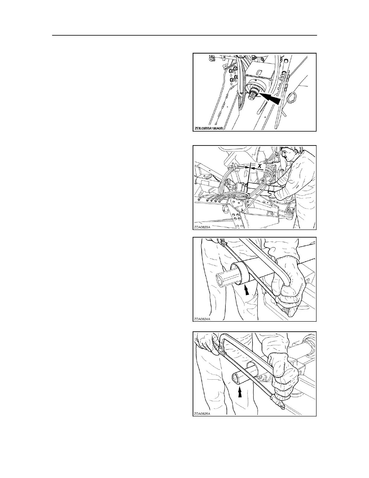
ATTACHMENT OF THE PTO SHAFT
Check proper length of the PTO shaft with the tractor
in straight line to ensure sufficient overlap of the
telescoping shafts (maintain a minimum overlap of
one third of the length of the telescoping shafts at all
times).
Make maximum possible turns to the left and to the
right and check proper length in the shortest working
position to avoid bottoming out of the telescoping
shaft and secondary damage to the PTO yokes.
Remove the front half of the PTO shaft from the baler.
Place the rear half in the PTO support.
Attach the baler to the tractor and make the sharpest
possible turn left or right as illustrated (Fig. 27).
Shut down the tractor.
Attach the front half of the PTO shaft to the tractor.
Hold both PTO halves along each other and check
distance X (Fig. 27).
28
If distance X gets below 20 mm (13/16 in), shorten the
PTO shaft as follows:
Determine the length of the PTO shafts to be cut.
Cut the plastic guards of both PTO halves to the
determined length (Fig. 28).
Cut the telescoping tubes by the same amount as the
guard (Fig. 29).
29