SECTION 2 - CONTROLS, INSTRUMENTS AND OPERATION
2ï20
File down sharp edges from the tube, remove any
swarf and thoroughly grease the telescoping tube.
IMPORTANT: Further modifications to the PTO shafts and
guards are not allowed.
30
Install the PTO shaft to the tractor as follows: • The front yoke of the driveline is equipped with a push-pull collar.
Connect the yoke to the tractor PTO shaft by pushing the locking collar to release the retaining device.
• Slide the yoke forward until the locking collar
automatically resets in its clamped position
on the groove of the tractor PTO shaft.
ATTENTION: To ensure the driveline is well clamped to the
tractor PTO shaft, move the front U-joint forward and
rearward. The front yoke should remain locked on the
tractor shaft.
To prevent any vibration on the driveline the front yoke
must be free of backlash on the tractor shaft. Replace any
worn parts as necessary.
Check for possible interference with baler tongue
components, hydraulic hoses and wiring looms.
NOTE: It is preferable to have a positive limitation on the
turning angle (i.e. tires contacting the baler tongue),
rather than having the possibility to exceed the PTO shaft
design capabilities.
IMPORTANT: Avoid sharp turning. If you can not avoid
this, lift the pick-up to stop crop intake and reduce or stop
the PTO speed.
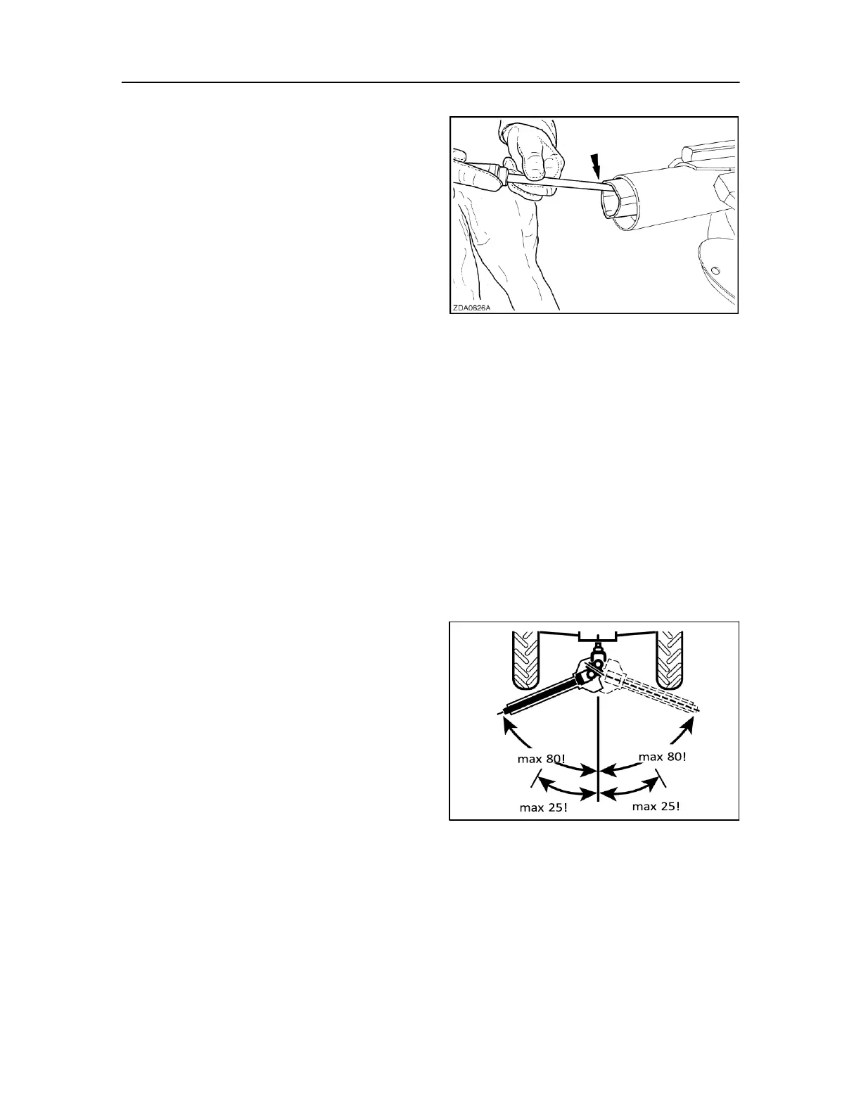
Restrict the PTO angle to:
• Maximum 80° when disengaged or running idle.
• Maximum 25° for continuous operation under
heavy load.