This check is performed by setting a magnetic−base dial gauge
(2) on the output shaft (3) as shown in the figure, standard
value is 0.068 to 0.41.
If higher value is found, replace main th rust half bearings of
the s econd last rear support (1) and repeat the clearance
check between ou tput shaft pins and main half bearin gs.
70188
70189
70190
70191
Figure 36
Figure 37
Figure 38
Figure 39
-
3rd stage, using acceptable tools (I) set as shown in the
figure, tighten the screws (2) with 90°±5° angle.
- Remove caps from supports.
The backlash between the main bearings and the pins is
found by comparing the width of the calibrated wire (2) at
the narrowest point w ith the scale on the envelope (1)
containing the calibrated wire.
The number s on the scale indicate the backlash in mm.
Replace the half bearings and repeat the check if a different
backlash value is found. Once the specified backlash is
obtained, lubricate the main bearings and fit the supports by
tightening the fastening screws as previously described.
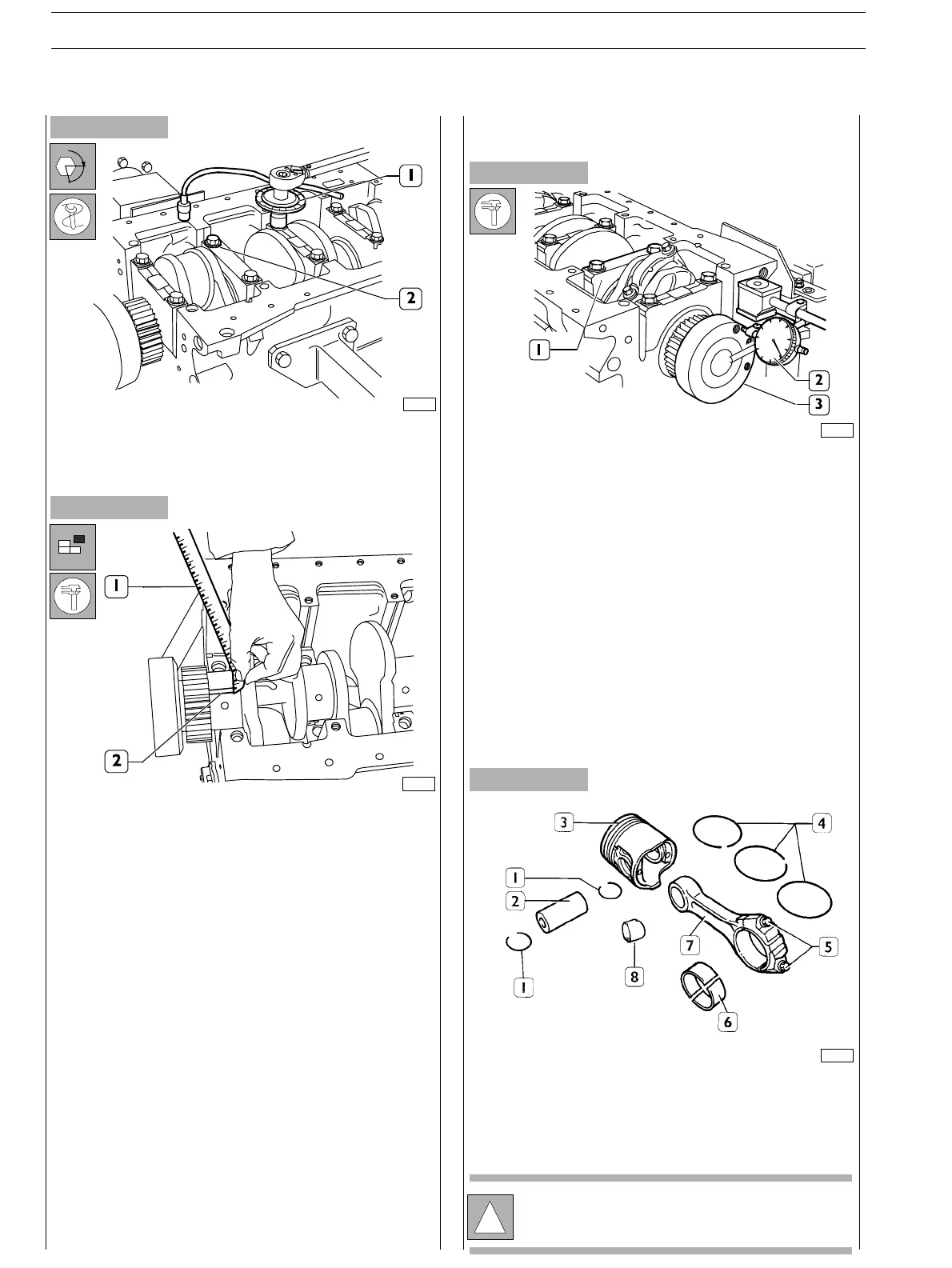
CONNECTING ROD — PISTON ASSEMBLY
COMPONENTS
1. Stop rings − 2. Pin − 3. Piston − 4. Split rings − 5. Screws
− 6. Half bearings − 7. Connecting rod − 8. Bush.
α
Checking output shaft shoulder clearance
!
Pistons are supplied spare with 0.5 mm oversize.
CONNECTING ROD — PISTON
ASSEMBLY
SECTION 4 − OVERHAUL AND TECHNICAL SPECIFICATIONS
22
E NG I NE S
ED. FEBUARY 2003