61696
61694
61695
70198
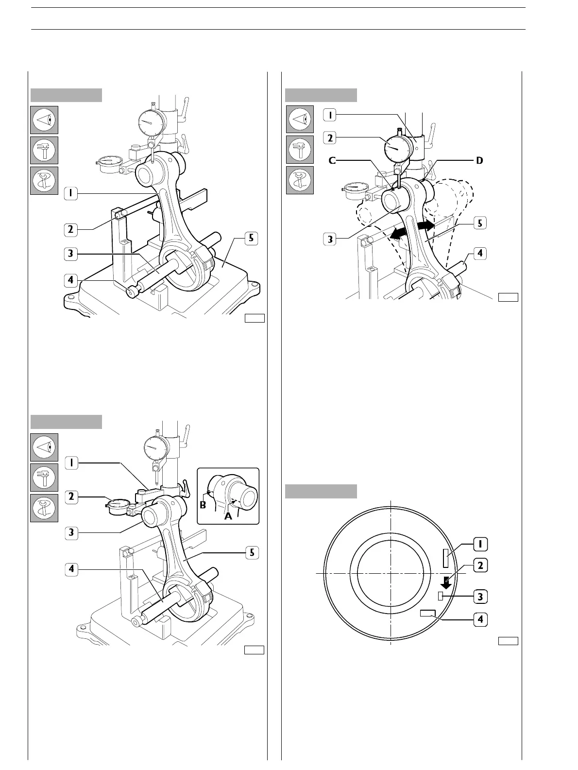
Figure 53
Figure 54
Figure 55
Figure 56
Check that the axes of the connecting rods (1) are parallel
u s in g acceptable tools (5) as fo llow s :
-
fit the connecting rod (I) on acceptable tool (5) spindle
and lock it with screw (4);
- set t he spindle (3) on V−blocks by resting the connecting
rod (1) on th e sto p bar (2).
Check c onnecting rod (5) torsion by comparing t wo points
(A and B) of pin (3) on the horizontal plane of the connecting
rod axis.
Position the dial gauge (2) s upport (1) to obtain a preload o f
approx. 0.5 mm on the pin (3) in point A and then set the
dial gauge (2) to zero. Move the spindle (4) with th e
connecting rod (5) and compare any deviation on the
opposite side (B) of the pin (3): the difference between A and
B shall not exceed 0.08 mm.
Checkconnectingrod(5)bendingbycomparingtwopoints
C and D of the pin (3) on the vertical plane of the connecting
rod axis.
Position the vertical support (1) of the dial gauge (2) to rest
the latter on pin (3), point C .
Move the c onnecting rod forwards an d backwards t o find pin
top position, then in this condition reset the dial gau ge (2).
Move the spindle with the c onnecting rod (5) and repeat the
check of the top point on the opposite side D of the pin (3).
The difference between point C and point D shall not exceed
0.08 mm.
Fitting connecting rod−piston assembly
Connecting rod−piston coupling
The piston crown is marked as follows:
1. Part number and design modification number;
2. Arrow showing piston assembling direction into cylinder
barrel, this ar row shall face the front key of the engine
block;
3. Mar king showing 1
st
slot insert testing;
4. Manufacturing date.
Checking connecting rods Checking bending
Checking torsion
SECTION 4 − OVERHAUL AND TECHNICAL SPECIFICATIONS
26
E NG I NE S
ED. FEBUARY 2003