50676
75759
75751
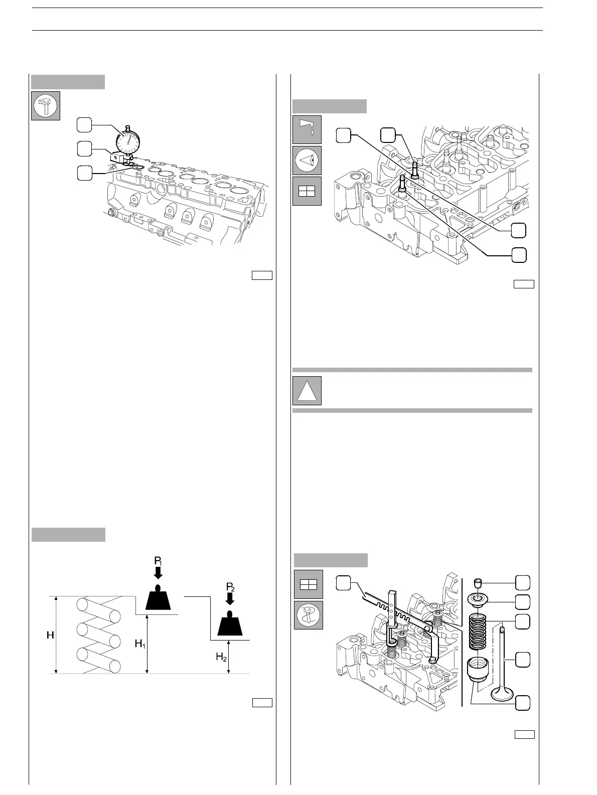
Figure 81
Figure 82
Figure 83
MAIN DATA TO CHECK INTAKE AND EXHAUST
VALVE SPRINGS
Before refitting use acceptable tools to check spring
flexibility. Compare load and elastic deformation data with
those of the new springs shown in the following table.
FITTING CYLINDER HEAD
Lubr icate the valve st ems (1) and fit them into the relevant
valve guides ac cording to the position marked at removal.
Fit the sealing rings (2 and 3) o n the valve guide .
Position on the cylinder head: the spring (4), the upper cap
(3); use acceptable tools (I) to compress the spring (4) and
lock the parts to the valve (5) by the cotters (2).
!
Sealing rings (2) for in take valves are yellow and
sealing rings (3) for exhaust valves are green.
VALVE SPRINGS
75758
Figure 84
After regrinding, check that valve (3) sinking valu e is the
specified one by using the base (2) and the dial gauge (I).
1
2
3
4
5
6
1
2
3
3
1
1
2
SECTION 4 − OVERHAUL AND TECHNICAL SPECIFICATIONS
34
E NG I NE S
ED. FEBUARY 2003