70326
18625
18882
75757
Figure 74
Figure 75
Figure 76
Figure 77
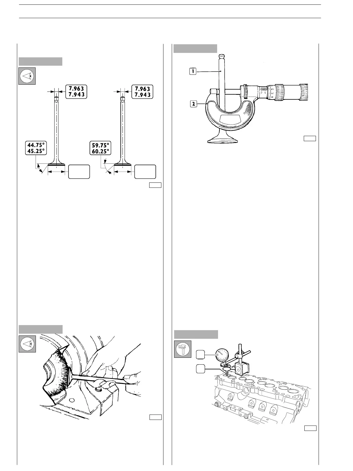
VALVES
INTAKE AND EXHAUST VALVE MAIN DATA
Remove carbon deposits from valves using the proper metal
brush.
Check that the valves show no signs of seizing, scoring or
cracking.
Regrind the valve seats, if required using acceptable
tools and removing as little material as possible.
Check the valve stem (1) using a micrometer (2), it shall be
6.960 to 6.980.
Use a magnetic base dial gauge (1) set as shown in the figure,
the assembling clearance sh all be 0.052 ± 0.092 mm.
Turn the valve (2) and check that the centering error is not
exceeding 0.03 mm.
Removing carbon deposits, checking and
grinding valves
Checking clearance between valve stem and
valve guide and valve centering
INTAKE
VALVE
EXHAUST
VALVE
42.13
41.87
45.13
44.87
2
1
SECTION 4 − OVERHAUL AND TECHNICAL SPECIFICATIONS
32
E NG I NE S
ED. FEBUARY 2003