Figure 31
Figure 32
- Screw up two medium length screws in the ports (4) to
slingtheflywheelwithahoist.
Throughout two guide pins (2) previously screwed up
into the engine drive shaft ports (3) control the engine
flywh eel withdrawal by means of a hoist.
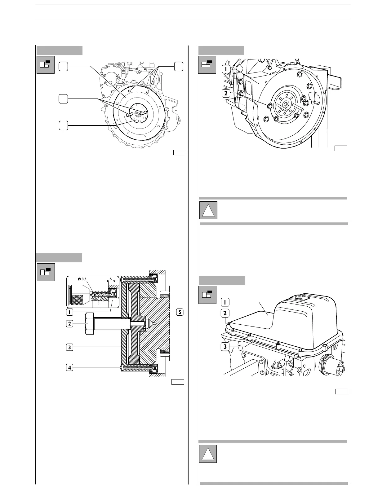
- Remove the flywheel cover box fixing r ing using the tool
380000663 (3) t o o per at e o n t h e bac k t an g (5) o f t h e
engine drive shaft. Throughout the tool guide ports, drill
the internal holding ring using Ø 3,5 mm drill for a 5mm
depth.
- Fi x t h e t o o l 380000663 (3) t o t h e r i n g (1) t igh t en in g t h e
6 screws specially provided (4).
- Proceed with drawing the ring (1) tightening the screw
(2).
-
Use acceptable tools (3) (4) and withdraw the external
holding ring of the flywheel cover box.
- Loosen the screws (2) and remove the flywheel cover
box (1).
!
Take note of the screw (1) assembly position, since
the screws have different length.
Figure 33
Figure 34
- Turntheengineupside−down.
- Loosen th e screws (2), disassemble the plate (3) and
remove the oil pan (1).
1
2
3
4
75690
00903t
70153
70154
!
The shape and dimensions of the pan and of the rose
pipe may vary according to the engine application.
The relating illustrations provide general guidelines
of the operation to be performed. The procedures
described are applicable anyway.
SECTION 3 − DUTY − INDUSTRIAL APPLICATION E NG I NE S
17
ED. FEBUARY 2003
zs