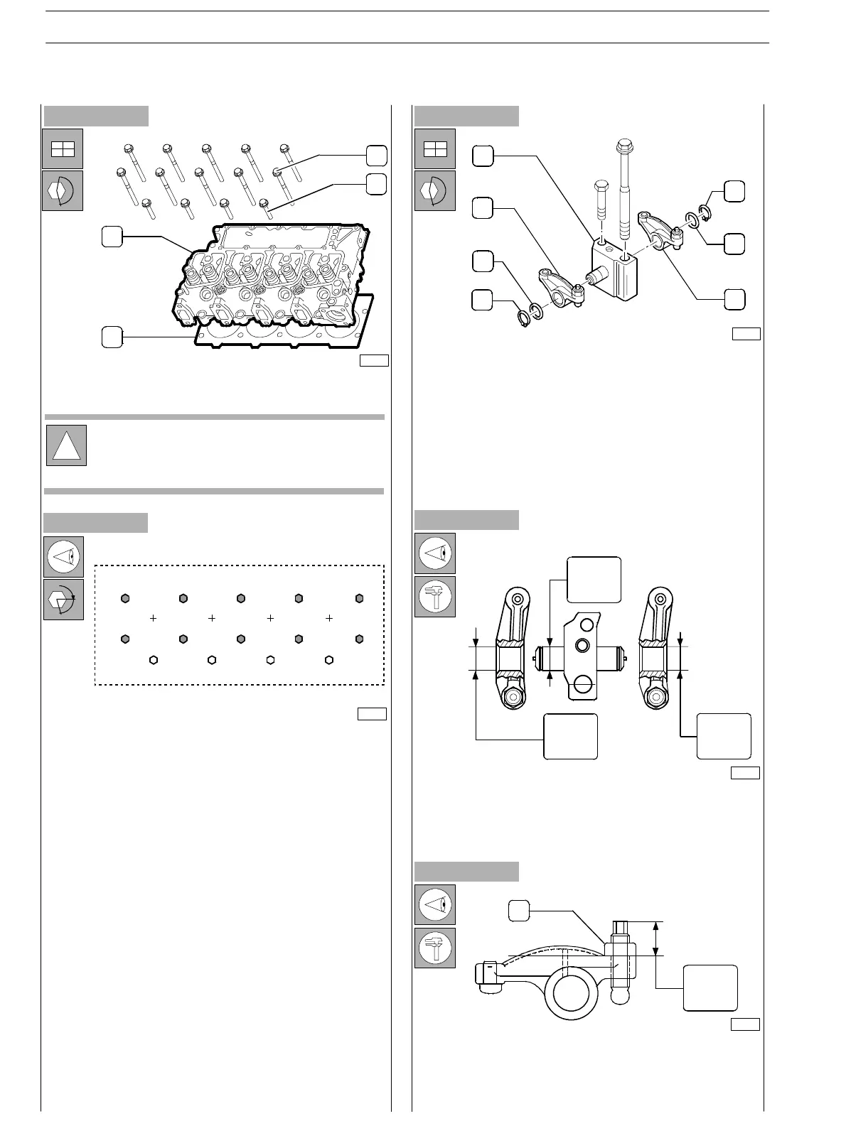
Figure 66
Figure 67
- Place the head (3) over the block and insert screws (1)
and (2).
- Lubricate cylinder head bolts an d install to head.
- Bolts must be torqued using stitching pattern starting
with the c entre bolts and moving out. Bolts to be
torqued in stages: all bolts torqued to snug torque, then
90 degrees rotation for all bolts. Then a further 90
degrees for the M12 x 140 and M12 x 180.
M12 x 70 50 Nm + 90 deg’s
M12 x 140 40 Nm + 180 deg’s
M12 x 180 70 Nm + 180 deg’s
Figure 68
SHAFT AND ROCKER ARM BASIC DATA
Check the coupling surfaces of bearing and shaft: no evidence
of excessive wear shall be detected or damages.
Replace if necessary.
- Carry out the assembly of the rocker arms after previous
check of the components.
Figure 69
!
If the valves have been removed from the head, it is
necessary to assemble them before assembling the
head itself on the engine block.
1
2
3
4
75688
75705
1
2
3
4
1
2
3
ROCKER ARM UNIT COMPONENTS:
1. Elasti c ring − 2. Spacer− 3. Rocker arms−
4. Support.
76115
1
2
3
45
6
7
8
9
10
11
12
13 14
α
75704
18.975
18.963
19.000
19.026
19.000
19.026
1
19.00
16.00
Figure 70
75702
ROCKER ARM ADJUSTMENT SCREW
If unscrewed, check adjustment quota.
Tighten the screw−threaded nut (1) to the i 0.25 − 0.75 Nm
couple.
SECTION 3 − DUTY − INDUSTRIAL APPLICATION
26
E NG I NE S
ED. FEBUARY 2003
zs