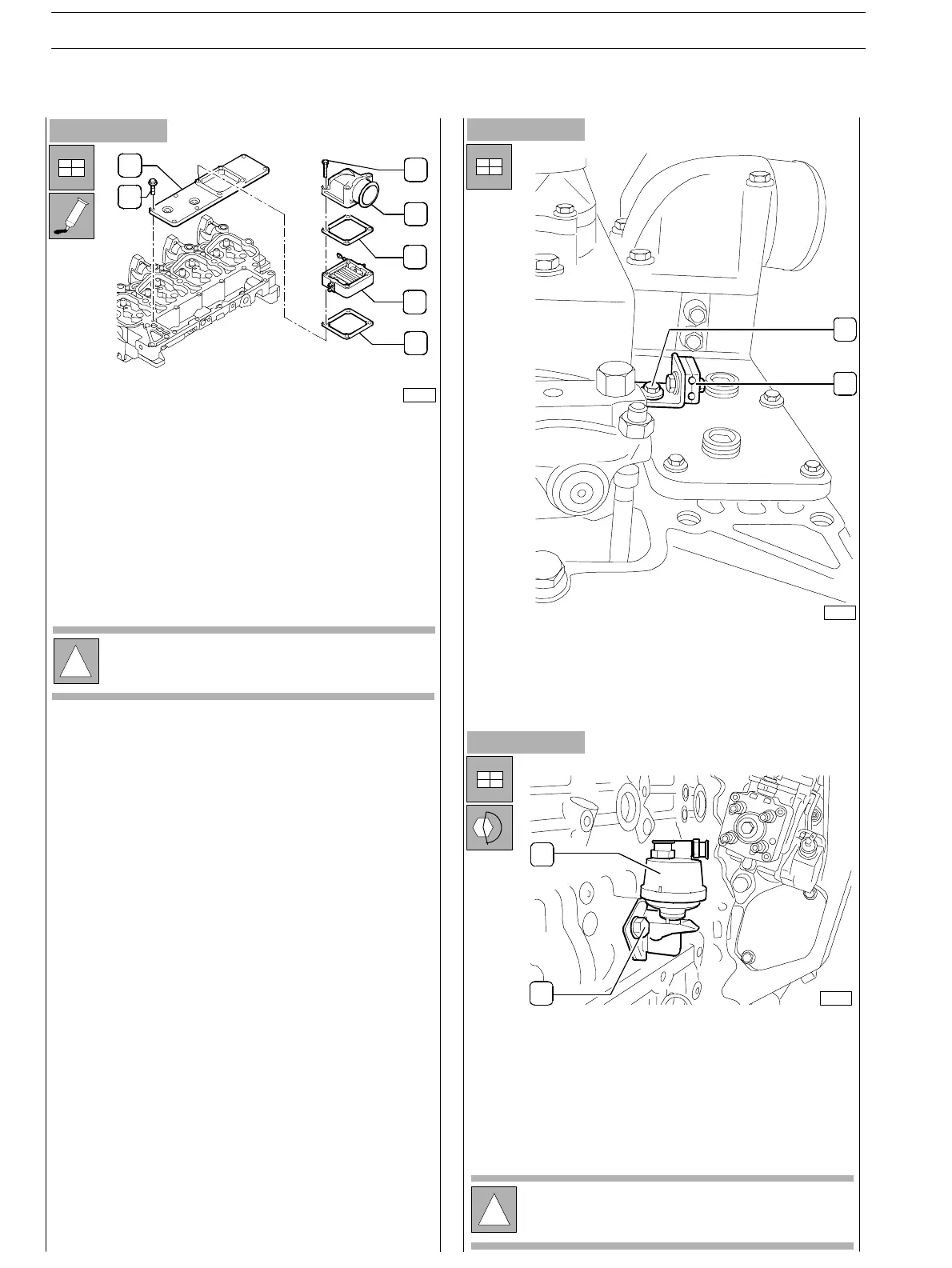
Figure 81
- Apply on the surface joining the suction manifold plate
(1) a sufficient coat of Loctite 5999 and provide. fixing
the screws to the prescribed couple.
- If the pipe (6) of the suction manifold plate (1) has been
removed, reassemble it after having fit a n ew gasket (5).
- Tighten the screws (7) to the prescribed couple.
Figure 82
!
For the version s provided with h eater, also assemble
components (3) and (4).
- Also assemble the brackets (1) fixing the fuel pipelines
to the injectors: use the same screws (2) fixing the
manifold plate as shown in th e picture.
Figure 83
- Assemble pr iming pump (1) providing new gasket and
tighten the screws (2) to the prescribed couple .
- Also assemble feed pump (see specific procedure) and
the power take−off underneath.
!
Pump assembly requires specific procedure as
reported at the end of the hereby section.
75701
75700
1
2
1
2
3
4
5
6
7
2
1
75678
SECTION 3 − DUTY − INDUSTRIAL APPLICATION
30
E NG I NE S
ED. FEBUARY 2003
zs