9
6. CIRCUIT EXPLANATION
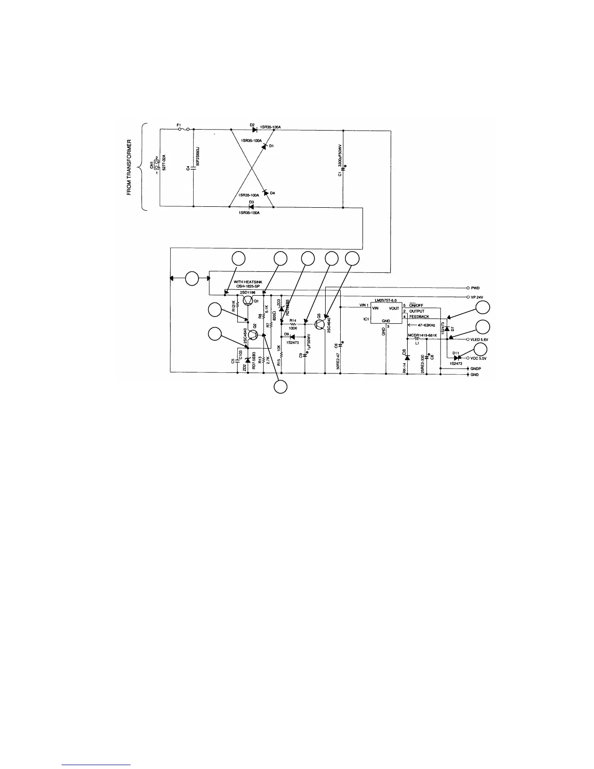
6-1. Power supply circuit
Q1 : Transistor for controlling voltage (VP)
Q2 : Transistor for voltage detection
Q3 : Transistor for controlling power down (PWD) signal
ZD2 : Zener diode for controlling base current of Q2
ZD3 : Zener diode for detecting power down (PWD) signal
After plug the AC cord into the outlet, the AC voltage (23.8V) appears at CN1 connector.
Then this voltage is rectified by the diode brige and it become constant voltage through the capacitor C1.
[Voltage VP]
A constant voltage (31.4V) appears on the “ 2 “ position. This voltage made from the constant
voltage circuit consist of transistor Q1 and Q2, zener diode ZD2, resisror R7, R8, R12 and R13.
[Voltage VLED and VCC]
The voltage goes to pin No.1 of regurator IC1 and then it is out from pin No.2 of IC1 as stable
voltage (5.6V).
Then this voltage down to 5 volts through the diode.
It is used for VCC ( for logic) and VLED (for display drive).
Also, it goes to pin No.4 of IC1 and using to control the output voltage level.
Inductor L1 is used to stabilize the VCC voltage when the drawer opened.
12
11
10
1
2