13
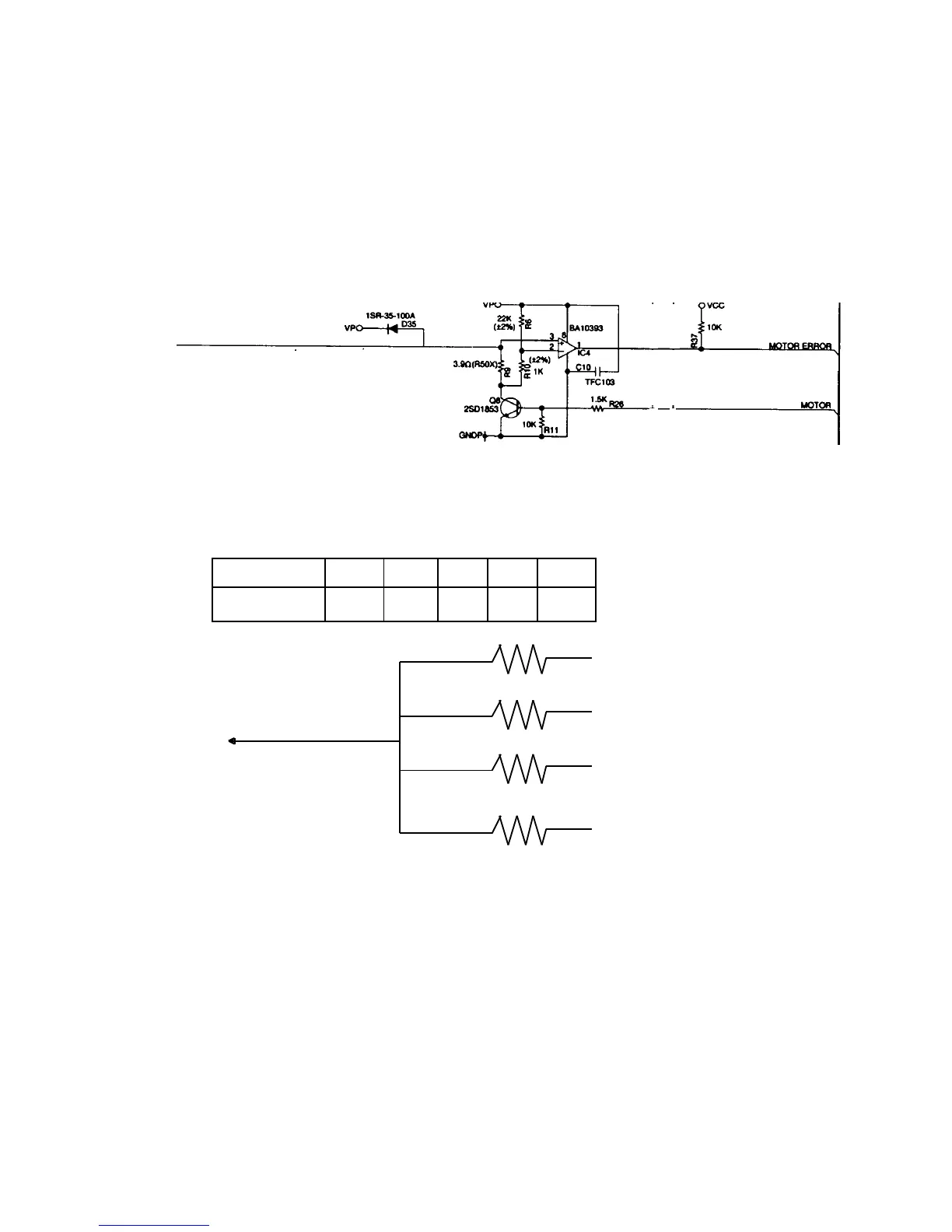
6-3. Motor error detection circuit
When the CPU output motor signal, transistor Q8 becomes on and the voltage level at “A” point
becomes GND. Then, paper feeding motor rotate. Normally, pin No.1 of IC4 appears low signal.
IC4 detects differential voltage between pin No.2 and 3.
In case pin No.3 is higher than No.2, output(Pin No.1) signal is hogh.
If motor happens over load ( Paper jam etc.), over load current (250mA) runs resistor R9.
So, “A” point voltage lebel becomes high.
Then IC4 outputs high signal and then CPU knows motor error occured.
When the CPU receives “Motor error signal”, CPU stops motor signal.
6-4. Mode key switch status read
The CPU knows the mode switch status by voltage level of pin No.1.
the voltage level is down by resistor. Each voltage is as shown below.