14
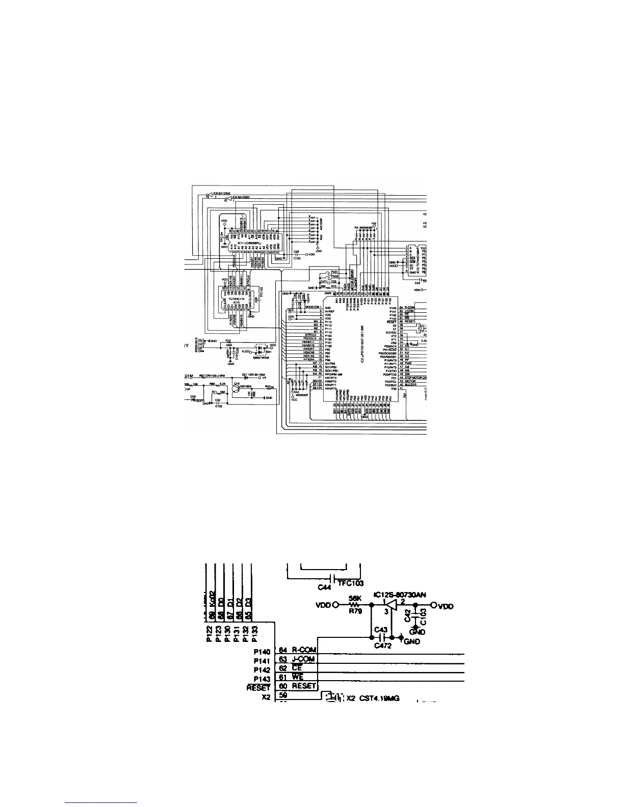
6-5. RAM address/head drive signal switching circuit
The CPU is used the port for RAM address (A0~A11) and head drive signal (HD1~HD6).
To select the RAM address and head drive signal, CPU use “STEP MOTOR COM” signal.
When CPU wants to read the RAM chips, CPU stops “STEP MOTOR COM” signal.
The CPU controls RAM address (A0~A12) using IC10 because of CPU has 7 ports.
First, CPU sneds RAM address (A4~A7,A10,A11) to IC10, and IC10 store the address data.
Next, CPU send RAM address (A0~A3,A8,A9,A12,A14) to RAM.
At the same time, CPU sendsclock signal to IC10.
Then, IC10 outputs stored data (A4~A7,A10,A11). In this way, CPU controls RAM address.
6-6. Initilize IC (Reset IC)
When the voltage level on pin No.60 of CPU is not sabilized, CPU does not work properly
in rare case.
Therefore, this machine uses the initilize IC for stabilizing the voltage.
Even the voltage level of VDD (Pin No.2) is changed of Initilize IC, initialize IC output stabilized
5 volts from pin No.1.