74
Appendix B: Command Tables
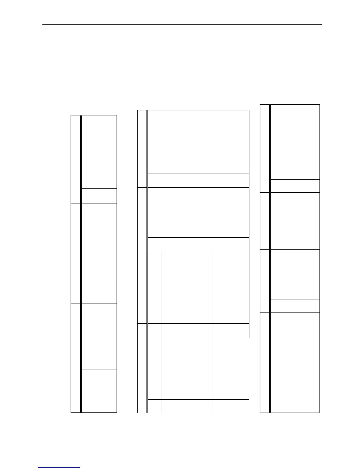
Command 3 - SAMPLE AND TRIGGER SETUP
!1 A sample time to 0.5 should be used whenever an external clock is specified as the clock source.
Sample Time Number of Samples Record Time
0.001 to 16000 Number of seconds –1 Real-time data sampling. * 0 Off
(* 0.5) 1 Absolute time recording
1 to 512 Number of samples 2 Relative time recording
(* 20)
Trigger Source Trigger Threshold Trigger Edge Clock Source
0 Off — 0 Falling edge * 0 Timer (sampling time)
* 1 Manual ([TRIGGER] key) * 1 Rising edge 1 [TRIGGER] key
2 CH1 (±10V) ±10 (V) 2 CH1 (±10V)
3 CH2 (±10V) ±10 (A) 3 CH2 (±10V)
4 CH3 (±10V) (default = 1) 4 CH3 (±10V)
5 CH1 (0-5V)
1 to 100 (k") 5 DIG IN clock
6 CH2 (0-5V) 0 to 5 (V)
7 CH3 (0-5V) (default = 1)
8 DIG IN clock —
9 DIG IN 4-bit data 0000 - 9999 (D3-D0)
0 : LOW
1 : HIGH
2 - 9 : Don't care
(default = 0001)
Clock Threshold Clock Edge Prestore Data % Filter
±10V 0 Falling edge 0 to 100 * 0 No filtering
±10A * 1 Rising edge (default = 0) 1 5-point S-G smoothing
(default = 1) 2 9-point S-G smoothing
3 17-point S-G smoothing
When a clock source (2, 3, or 4) 4 25-point S-G smoothing
is specified for an analog channel. 5 3-point median filtering
6 5-point median filtering