— 11 —
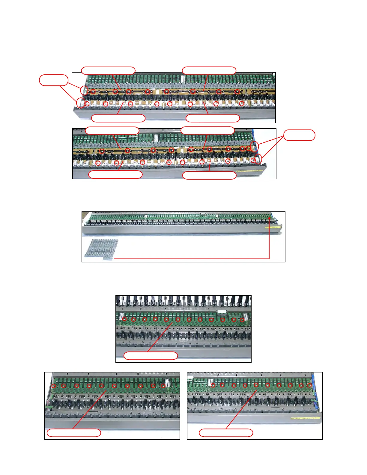
■ Removing the LED PCB (MPCK-LDA1~LDA4, LDB5~LDB8)
23. Remove four connectors.
24. Remove four screws and the PCB for each PCB.
* As for MPCK-LDA4 only, remove five screws.
■ Removing the KEY PCB (MPCK-KYA1, KYB2, KYA3)
25. Remove the rubber key.
* One of them has a different length.
26. Remove ten screws and then the KEY PCB (MPCK-KYA1).
27. Remove 12 screws and then the KEY PCB (MPCK-KYB2).
28. Remove ten screws and then the KEY PCB (MPCK-KYA3).
MPCK-KYA1 PCB
MPCK-KYA3 PCB
Connector
MPCK-LDA2 PCB
MPCK-LDA1 PCB
MPCK-LDB6 PCBMPCK-LDB5 PCB
Connector
MPCK-LDA3 PCB
MPCK-LDA4 PCB
MPCK-LDB7 PCB
MPCK-LDB8 PCB
MPCK-KYB2 PCB