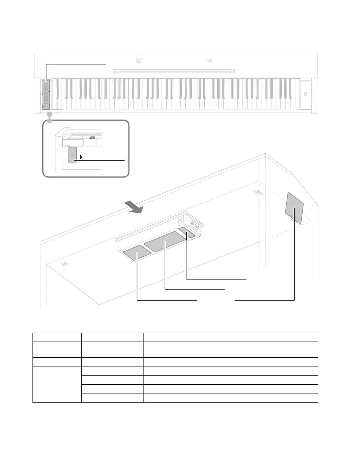
EasyManuals Logo

Casio PX-720 User Manual

Casio PX-720
34 pages
To Next Page IconTo Next Page
To Previous Page IconTo Previous Page
Page #5 background imageLoading...
Page #5 background image
– 3 –
PCB LAYOUT
PCB Components
MAIN PCB M408-MDA1 MPU, Reset IC, RAM(64Mbit), FLASH memory(128Mbit),
ROM(16Mbit), DAC, Key controller
SUB PCB M408-PSA1 Power supply circuit, Filter, Power amplifer
Console PCBs M681-CNA1 Button, Main volume
M681-CNA2 Phones jack
M681-CNA3 DC 12V terminal, MIDI OUT/IN terminals
M681-CNA4 Power lamp
Rear
M408-MDA1 PCB
M681-CNA1 PCB
M68
1-
C
NA4 P
CB
M681-CNA2 PCB
M681-CNA3 PCB
M408-PSA1 PCB

Questions and Answers:

Question and Answer IconNeed help?

Do you have a question about the Casio PX-720 and is the answer not in the manual?

Casio PX-720 Specifications

General IconGeneral
BrandCasio
ModelPX-720
CategoryMusical Instrument
LanguageEnglish

Related product manuals