Do you have a question about the Casio PX-720 and is the answer not in the manual?
Details the key matrix mapping for the electronic keyboard.
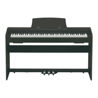
Illustrates and labels the piano keys.
Defines the functions of the buttons and their associated signals.
Details the process for disassembling the speaker box.
Instructions for removing the T-BRD unit from the main body.
Procedure for removing the keyboard's key cover and stoppers.
Steps to remove the main, sub, and console PCBs.
Procedure for removing the left and right side blocks.
Steps for removing the keyboard assembly and individual keys.
Steps to prepare the unit before starting diagnostic tests.
Instructions on how to activate the diagnostic program.
Details the automatic testing sequence for system components.
Checks the internal and external ROM versions.
Verifies the headphone output functionality.
Checks MIDI input/output functionality.
Schematic diagram for the main PCB.
Schematic diagram for the sub PCB.
Schematics for console PCBs CNA2, CNA3, and CNA4.
Schematic diagram for the console PCB M681-CNA1.
| Brand | Casio |
|---|---|
| Model | PX-720 |
| Category | Musical Instrument |
| Language | English |