— 30 —
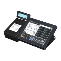
D. Assembling COM PCB (E830-COM)
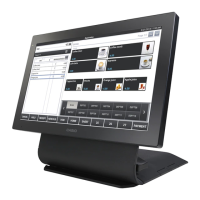
D-1. Install three COM PCBs (E830-COM) and secure them with two nuts each.
D-2. Plug two connectors and the FPC.
Screws (S5)
Screws (S5)
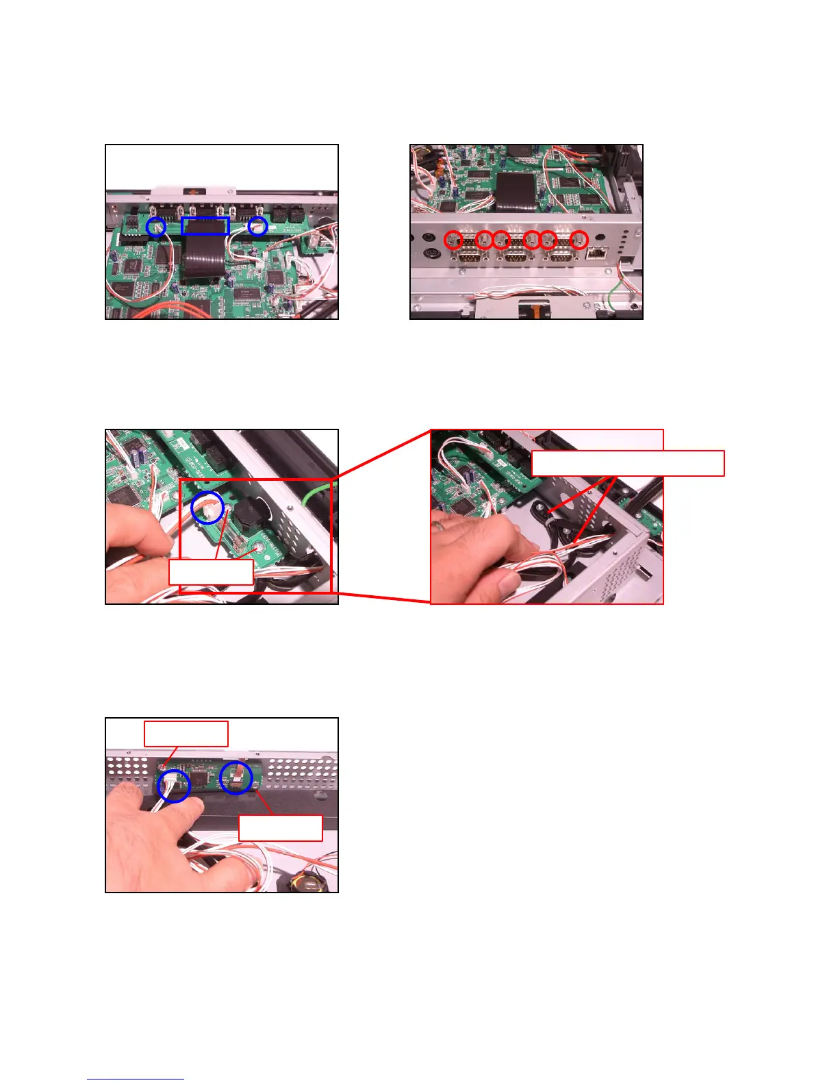
E. Assembling the Power Supply PCB (E830-INLET)
E-1. Engage the Power Supply PCB (E830-INLET) and secure it with two screws.
NOTE: two Drawer Cables are arranged under the PCB.
E-2. Plug the connector.
F. Assembling the Touch Panel PCB (E830-TP)
F-1. Engage the Touch Panel PCB (E830-TP) and secure it with two screws.
F-2. Plug the connector and 1 FPC.
NOTE: Engage the FPC securely until it locks in.
Drawer cables
Screws (S5)
 Loading...