Check for parts online at www.castlestoves.com or call 800-450-EDGE (3343) M-F 8-5
14
Operator's Manual
Serenity Pellet Stove
NOTE: In order to achieve optimum performance, it is
recommended that you keep the vent as short as
possible, especially in regards to the horizontal
run.
The vent must have a support bracket every 5’ of pellet vent when
on the exterior of the structure.
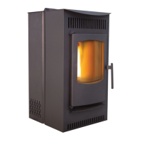
The vent height and run must not exceed the distance as
illustrated in the diagram below.
Venting into this (the lighter) shaded area may require
combustion motor voltage adjustments and/or inlet air
adjustments (intake). SEE FIGURE 9.
Venting The Pellet Stove (See Figures 8 through 16.)
33 Feet
(max.)
30 Feet
25 Feet
20 Feet
15 Feet
10 Feet
5 Feet
0 Feet
0 Feet
5 Feet
10 Feet
(max.)
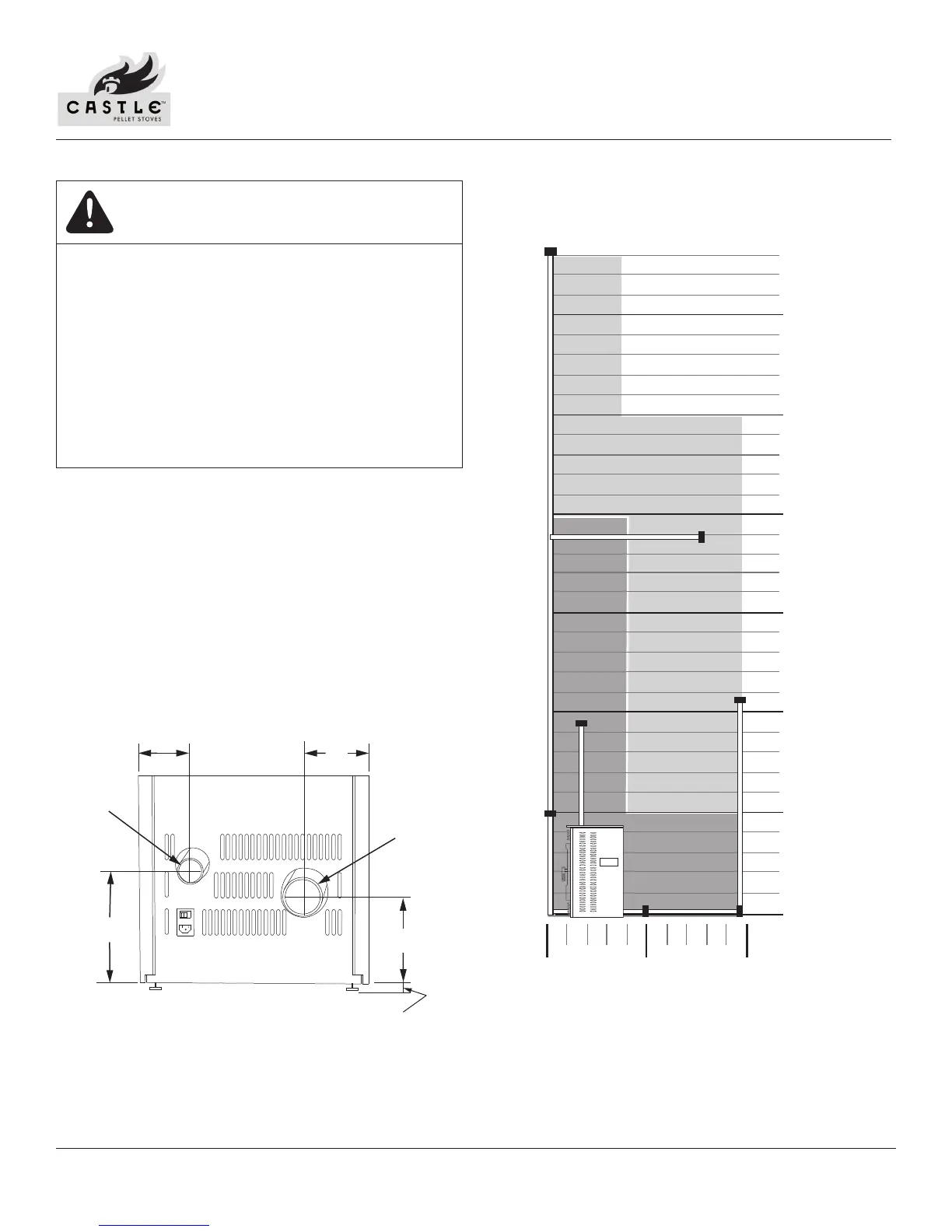
Figure 8: Intake and Exhaust Positions
Figure 9: Venting and Combustion Motor Voltage Adjustment Chart
MAKE SURE PELLET STOVE IS VENTED CORRECTLY.
DO NOT INSTALL FLUE DAMPER IN THE EXHAUST
VENTING SYSTEM OF THIS UNIT.
USE AN APPROVED WALL THIMBLE WHEN PASSING
THE VENT THROUGH WALLS. USE A CEILING
SUPPORT/FIRE STOP SPACER WHEN PASSING THE
VENT THROUGH CEILINGS MAKE SURE TO MAINTAIN
CLEARANCE TO ANY COMBUSTIBLES.
IF USING MORE THAN ONE TEE AND 180
O
OF ELBOWS,
YOU MUST USE 4“ VENTING PIPES.
CAUTION
8”
4”
2” DIA
9 3/4”
4 1/4”
3” DIA
NOTE: THE ADJUSTABLE FOOT PAD CAN ADD UP TO
1 INCH TO HEIGHT MEASUREMENTS DEPENDING
ON YOUR INSTALLATION LEVELING REQUIREMENTS.
THIS DIMENSION MUST BE ADDED TO THE HEIGHT
FOR PROPER INSTALLATION OF VENT PIPES.