Do you have a question about the CBE Avida PC220-KT and is the answer not in the manual?
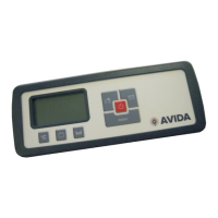
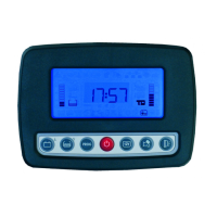
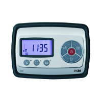
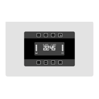
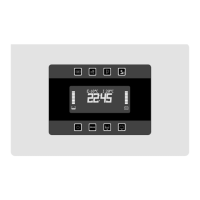
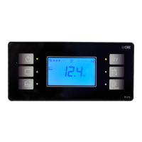
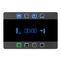
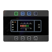
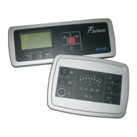
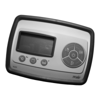
Details the buttons, indicators, and main functions of the control panel.
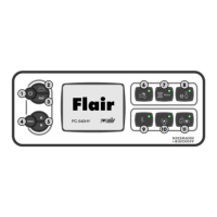
Lists and describes the protection fuses within the 12V distribution box.
Provides information on the battery charger's function and requirements.
Describes the electronic probe used for measuring water tank levels.
Details the leisure battery's role in powering various users and systems.
Explains the function of the chassis battery as the primary power source.
Describes how the engine alternator recharges both battery types.
Information on the 240V circuit breaker for switching and protection.
Details the fuses protecting the chassis and leisure batteries.
Safety and maintenance advice for handling, charging, and checking batteries.
Guidelines for safe installation, operation, and ventilation of the battery charger.
Recommendations for preventing fouling in water tanks.
Safety procedures for maintenance and operation of the 240V circuit breaker.
Instructions for fuse replacement and troubleshooting blown fuses.
Detailed description of each button's function on the control panel.
Explanation of the status indicators and LED lights on the control panel.
Explanation of various icons and symbols shown on the main display.
Details on what the digital display shows, including clock and units.
Description of the low voltage alarm for the chassis battery.
Information on how the chassis battery is recharged.
Description of the low voltage alarms for the leisure battery.
Details on how the leisure battery is charged via alternator, mains, or solar.
Explanation of the device that cuts off 12V fuses at low voltage.
Describes the device that parallels batteries based on voltage.
Details on how the amperemeter measures current and its measurement range.
Explanation of the red LED indicator for broken fuses.
Instructions on how to enter the system setting mode.
Procedure for setting the clock's hours and minutes.
Procedure for setting all system parameters.
Instructions for selecting the backlight colour of the display.
Instructions for activating or deactivating acoustic alarms.
Procedures for setting internal and external temperatures.
Procedure for calibrating the amperemeter to zero.
Instructions for adjusting the leisure and chassis voltmeter readings.
Detailed list and description of each protection fuse and its rating.
Explanation of the AES fridge connection and its bypass function.
Description of the output for controlling auxiliary relays when the engine starts.
Details on connecting various user outputs like RH, Multimedia, TV, and lights.
Instructions for connecting the waste water tank probe.
Instructions for connecting the electronic waste water probe.
Instructions for connecting the drink water electronic probe.
Information on connecting the control panel to the 16-pole connector.
Details on signal inputs for engine starting and battery charger.
Wiring details for the awning light and OUT D+ connection.
Instructions for connecting to mains' earth and vehicle earth.
Instructions for connecting to the services and chassis batteries.
Information on connecting the 12V exit to power sources.
Visual representation of the electrical system components and connections.
Diagram showing connections between the control panel, distribution box, and batteries.
| Brand | CBE |
|---|---|
| Model | Avida PC220-KT |
| Category | Control Panel |
| Language | English |