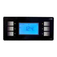
The CBE PC320-ST is a control panel designed for recreational vehicles, offering comprehensive management of the electrical system, water tanks, and various other functions. It integrates with a distribution box (DS300-ST) to provide a centralized control point for the vehicle's essential systems.
Function Description
The PC320-ST control panel serves as the primary interface for monitoring and controlling the electrical system, water levels, and other functionalities within a caravan or motorhome. It displays key information such as battery voltage (leisure and car batteries), fresh and waste water tank levels, internal and external temperatures, and time. The panel allows users to activate and deactivate various loads, including lights, water pump, heating/boiler, and other 12V appliances. It also features an alarm clock and programmable settings for user preferences.
The system comprises several main components:
- Control Panel PC320-ST: The user interface for monitoring and control.
- Distribution Box DS300-ST: The main relay and fuse box, managing power distribution and protection.
- Battery Charger: A device for charging the leisure battery.
- Electronic Tank Probe: Measures the content of fresh and waste water tanks.
- Tank Probe with Screws "SS/P": Signals the level of the waste water recovery tank.
- Leisure Battery "B2": Powers all users.
- Car Battery "B1": The vehicle's starting battery.
The system supports smart alternator functionality, allowing for optimized charging of both leisure and car batteries, especially in vehicles equipped with SMART ALTERNATOR systems (present on all DS300 distribution boxes manufactured since September 2019). This intelligent system manages D+ functions (parallel batteries, OUT D+ simulated output, awning light, etc.) and ensures proper charging conditions.
Important Technical Specifications
The PC320-ST control panel operates on a 12V system. The distribution box DS300-ST includes various protection fuses for different circuits:
- 5A fuse for external light.
- 10A fuse for the water pump.
- 10A fuse for heating/boiler.
- 20A fuse for lights group "A".
- 20A fuse for lights group "B".
- 30A fuse for 12V AES and 3-way function fridge.
- 20A fuse for auxiliary power supply (solar regulator).
- 25A fuse for the electrical step power supply.
- 3A fuse for gas power supply (fridge, kitchen, boiler valve, etc.).
- 3A fuse for OUT D+ simulated exit protection.
The system is designed to handle various battery types, including lead-acid and GEL batteries, with specific recommendations for maintenance and charging. The voltage settings for both leisure (B2) and car (B1) batteries can be calibrated, allowing for adjustments of +/- 0.5V in 0.1V steps.
The display shows temperatures in Celsius, with internal and external temperature settings adjustable in 0.5°C steps. The backlight brightness is also adjustable from 0% to 100%.
Usage Features
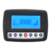
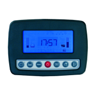
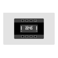
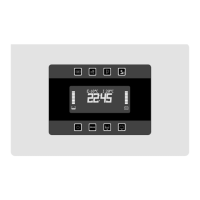
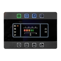
The control panel features a clear digital display and seven push buttons for navigation and control:
- Button for control of car and leisure batteries voltage (in Volt) and for the regulation of the programmable parameters' setting (see SETTING).
- Button for the control of fresh water tank (in %) and for fresh water-filling function operation (see "FRESH WATER TANK REFILLING" function) and for the regulation of the programmable parameters' setting (see SETTING).
- "PROG" button for system setting (see SETTING).
- On/Off main button (to turn on/off press for 2 seconds): at the start-up the display carries out a functioning test and shows all symbols (including unused symbols). If the relevant LED is green the control panel is on, if it is red an alarm is on (batteries, tanks, etc.).
- "12V" button to switch the lights and the heating/boiler on and off.
- Button to switch the pump on and off.
- Awning light button: this ext. light switches automatically off when you start up the engine, depends on the button rif.5.
The display provides a wealth of information:
- 230V net connection indicator.
- Car battery recharging unit activation.
- Battery parallel activation (engine on).
- Engine on indicator.
- External temperature digital indicator.
- Internal temperature digital indicator.
- Clock digital display.
- Setting menu indicator.
- Tones off indicator.
- Alarm clock display.
- Fresh water tank status display.
- "B2" leisure battery status display.
- Fresh water tank empty indicator.
- Waste water tank full indicator.
- Minimum voltage device indicator.
- Car battery (B1) run down indicator.
- Leisure battery (B2) run down indicator.
User settings include clock and alarm clock adjustments, backlight color and brightness, acoustic alarm activation/deactivation, and temperature calibration. The programming menu is accessed by pressing the "PROG" button for more than 2 seconds.
Maintenance Features
The manual emphasizes the importance of maintenance being carried out by specialized personnel, especially for electrical system interventions and 230V alimentation line work.
Batteries:
- Regularly check the instructions for use and maintenance provided by the battery manufacturer.
- Battery acid is corrosive; avoid contact with skin and eyes.
- If the battery is completely discharged, it needs recharging for at least 10 hours. If discharged for more than 8 weeks, it may be damaged.
- Periodically check the liquid level of lead-acid batteries. GEL batteries do not require maintenance but continuous recharging.
- Check the correct tightening of the connection binding screw and brush off any oxide.
- If the leisure battery is removed, isolate the positive pole to avoid short-circuits during accidental engine starting.
- In case of a longer stop, the service battery has to be disconnected or recharged regularly.
Battery Charger:
- The battery charger must be installed in a dry and ventilated place.
- Installation must be carried out by specialized technicians.
- In case of battery charger's misuse, the guarantee falls and the manufacturer declines all responsibility for damages to people and things.
- Do not carry out any maintenance when the battery charger is connected to the 230V power supply net.
- Do not cover air intakes and ensure an appropriate ventilation.
- Before disconnecting the battery charger from 230V power supply, turn the security switch off.
Tank Probes:
- Never let water in the tanks for long time, in order to avoid foulings, especially in the waste water tank.
230V Cut-Out Box:
- Before taking away the cover, check that the 230V socket is disconnected.
- In order to avoid damages to the box, check the correct tightening of the connections.
- In order to cut power to the whole 230V system, please take out the 230V main switch must be in the "0" (OFF) position.
- Connect and disconnect the external 230V net only when the main switch is off.
- In case of automatic switch break, find the damage before giving power again to the electrical system.
Fuses:
- Replace the fuses after finding out the real cause of the damage only.
- Only fuses are replaced respect the value of the amperage established.
Important Installation Note:
In case of installation of equipment that necessitate the deactivation of the permanent parallel relay (ref. 1), it is necessary to remove the R37 resistor (ref. 2). The resistor can be removed using a wire cutter, being careful not to damage the PCB traces below.