EasyManua.ls Logo

ccei MPZ - User Manual

ccei MPZ
16 pages
Print Icon
To Next Page IconTo Next Page
Loading...
Technical instructions
MPNT0255 v1.1 (10/03/2015)
MPZ
smart controller for
piezoelectric switch
Reference: SF10M070 / PF10M070
Table of Contents
1. Packaged content ................................................................................................................... 2
2. Technical features ................................................................................................................. 2
3. Description ............................................................................................................................ 3
3.1. Presentation of the MPZ ............................................................................................ 3
3.2. Description of components ......................................................................................... 4
4. Installation ............................................................................................................................. 5
4.1. Integration in a fuse box ............................................................................................ 5
4.2. Electrical connection .................................................................................................. 5
5. Configuration ........................................................................................................................ 7
5.1. Piezoelectric RGB markers ......................................................................................... 8
5.2. Mode of operation .................................................................................................... 10
5.3. Time out ................................................................................................................... 11
6. Operation ............................................................................................................................. 12
6.1. Start-up ..................................................................................................................... 12
6.2. Use ........................................................................................................................... 12
6.3. RGB LED command ................................................................................................ 13
6.4. Multi-function module indicator ............................................................................... 15
A. Declaration of Conformity ............................................................................................... 16
Read all of this leaflet carefully before installing, operating or using this prod-
uct.
Question and Answer IconNeed help?

Do you have a question about the ccei MPZ and is the answer not in the manual?

Summary

Description

Presentation of the MPZ

Introduces the MPZ smart controller and its typical applications.

Description of components

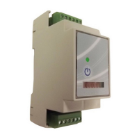
Details the parts of the MPZ controller, including indicators and keys.

Installation

Integration in a fuse box

Instructions for mounting the MPZ controller onto a DIN rail within a fuse box.

Electrical connection

Guidance on connecting the piezoelectric switch and power supply to the MPZ.

Configuration

Piezoelectric RGB markers

Explains how to activate and configure the marker mode for button lighting.

Mode of operation

Details how to select operating modes like remote control or sequencer using switches.

Time out

Describes how to configure time delay settings for the MPZ controller.

Operation

Start-up

Procedure for powering up the MPZ controller after configuration.

Use

How to operate the MPZ controller using the piezoelectric button or local control.

RGB LED command

Explains the meaning of different RGB LED colors and patterns on the button.

Multi-function module indicator

Describes the status indications provided by the multi-function LED on the MPZ.

Declaration of Conformity

Overview

The MPZ is a smart controller designed for piezoelectric switches, serving as a receiver that enables the control of two relays (normally open, Form A contacts, open in stand-by). It is commonly used to manage pumps for pool filtration, fountains, counter-current pools, massage pumps, or lighting systems.

Function Description:

The MPZ controller offers various operating modes, including:

  • Non-time delay remote control switch: Simple on/off control without a timed shutdown.
  • Time delay remote control switch: Allows for a timed shutdown after activation, with several time-out durations available.
  • Non-time delay sequencer: Provides sequential control of outputs without a timed shutdown, offering a choice of several sequences.
  • Time delay sequencer: Combines sequential control with timed shutdowns, offering multiple sequences and time-out options.

A key feature of the MPZ, when used with an illuminated piezoelectric switch (monochrome or RGB), is its ability to indicate the status of its two output points through the button's lighting or color. This marker lighting is configurable, aiding in switch detection and status awareness. The device also includes a front panel button for local command, providing an alternative control method.

Important Technical Specifications:

  • Power Supply: Operates on 85 to 265V~ AC from 7 to 440Hz.
  • Power Consumed: Maximum of 6W.
  • Overall Dimensions: 90 x 36 x 56 mm (2 DIN modules).
  • Weight:
    • Controller only: 100g (with unpluggable terminal blocks).
    • Full box: 280g.
  • Installation: Designed for standard DIN rail (OMEGA rail) in a fuse box, occupying 2 DIN modules in width.
  • Protection Index: IP-10 (requires integration into a fuse box).
  • Compatible Buttons:
    • Simple (no lighting).
    • With 12VDC monochrome LED lighting.
    • With 12VDC RGB LED lighting.
  • Output Points: Features 2 non-independent and configurable contact points.
    • Maximum output: 250VAC/3A resistive or 30VDC/3A resistive.
  • Mode of Operation: Remote control switch or sequencer, with a choice of several modes, including time delay or not.
  • Duration of Time Out: Configurable with options for deactivated, 3s, 30s, 3min, 15min, 30min, 1h, 2h, 4h.
  • RGB Markers When Off: Configurable by a choice of 6 modes.

Usage Features:

  • Configuration: Access to configuration switches requires unclipping the front panel with a flat screwdriver. Switches No. 1 and No. 2 select the operating mode, while Switch No. 3 activates or deactivates the time delay mode. Switches No. 4, 5, and 6 select the time-out duration or the RGB marker mode.
  • Piezoelectric RGB Markers: The "marker" mode activates RGB lighting on the piezoelectric button when the controller is in its initial "off" position (Seq. 1). This helps detect the button. Marker modes are selected by configuring switches 4, 5, and 6, then pressing and holding the front button while powering up, and finally releasing the button. The button's RGB lighting flashes a specific color to validate the selection.
  • Operation (Start-up): Upon power-up, the MPZ performs a color gradient on the RGB lighting (if available), followed by four flashes indicating the marker operating mode. The module and RGB lighting then assume their initial status (Seq. 1). After a power cut, the device always restarts in this "off" status.
  • Operation (Use): Each impulse from the piezoelectric button or press of the local control advances the module through its programmed sequences. Once the final sequence is reached, the next command returns it to the initial status (Seq. 1). If a time-out is selected, a timer starts with each button press, and if no further activity is detected, the module returns to its initial status (Seq. 1) after the programmed duration.
  • RGB LED Command: If RGB lighting is connected, the button lights up according to specific conditions:
    • Colour gradient: During power-up.
    • OFF/marker: No active output, no button pressed.
    • Red flash: Detection of a pressed button (piezo or local).
    • Blue (fixed or flashing): PZ1 output active.
    • Green (fixed or flashing): PZ2 output active.
    • Cyan (Blue+Green): PZ1 and PZ2 output points active.
    • Users can change colors by crossing the R/G/B threads in the output of the controller.
  • Multi-function Module Indicator: A front-side indicator displays the module's status:
    • Switched off: No electrical supply.
    • Regular flash (1 flash every 5 seconds): Stand-by, waiting for activation, both output points off.
    • Flashing (every second): In time delay mode, time-out in progress, at least one output point active, returning to initial position at end of time-out.
    • Switched on: In non-time delay mode, at least one output point active.

Maintenance Features:

The manual emphasizes the importance of reading the leaflet carefully before installation, operation, or use. It also states that installing the product could expose users to electric shock and strongly recommends using a qualified professional for installation to prevent damage to the product and connected equipment.

Installation Guidelines:

  • The MPZ must be installed on a standard DIN rail (OMEGA rail) within a fuse box and cannot be used as a standalone device.
  • The module clips onto the rail automatically.
  • For safety, and according to NF C15-100 standard, the fuse box housing the MPZ must be located:
    • More than 3.5 meters from the edge of a pool (measured taking into account obstacles and requiring distance to go around and reconnect if behind a wall).
    • Or in an underground room close to the pool, accessible by a trap door requiring a tool to open.
  • The controller must not be installed directly outside or inside; it needs to be integrated into a fuse box protected from rain, cleaning sprays, watering, and UV rays.
  • The fuse box must be on a flat, stable support firmly attached to a wall or its support.
  • Electrical connections involve connecting the piezoelectric switch to the top terminal block and the power supply and output points to the bottom terminal block.
  • Crucially, to control projectors through a transformer, a relay/switch mechanism must be installed. Do not directly power a transformer through the output points of the MPZ.

ccei MPZ Specifications

General IconGeneral
Brandccei
ModelMPZ
CategoryController
LanguageEnglish

Related product manuals