4
Persons fitted with pace-makers, hearing aids and similar equip-
ment must consult their doctor before going near a machine in op-
eration. The environment in which the equipment is installed must
be suitable for the casing’s protection level. This system is cooled
by means of the forced circulation of air, and must therefore be
placed in such a way that the air may be easily sucked in and ex-
pelled through the apertures made in the frame.
The welding unit is characterised by the following levels:
•
Protection level IP 23 S indicates that the equipment can be used
both indoors and outdoors.
•
Use class means that the equipment can be used in condi-
tions subject to heightened electrical shock.
Connection to the electrical supply
Before connecting the welder to the electrical supply, check
that the machine’s plate rating corresponds to the supply volt-
age and frequency and that the line switch of the welder is in
the “O” position.
Connection to the power supply must be carried out using the trip-
olar cable supplied with the system, of which:
•
2 conducting wires are needed for connecting the machine to
the supply.
• The third, which is YELLOW GREEN in colour is used for mak-
ing the “EARTH” connection.
Connect a suitable load of normalised plug (2P + e) to the
power cable and provide for an electrical socket complete
with fuses or an automatic switch. The earth terminal must
be connected to the earth conducting wire (YELLOW-GREEN)
of the supply.
Table 2 shows the recommended load values for retardant sup-
ply fuses.
NOTE 1: Any extensions to the power cable must be of a suitable
diameter, and absolutely not of a smaller diameter than the spe-
cial cable supplied with the machine.
NOTE 2: It is not advisable to plug up the welder to motor-driv-
en generators, as they are known to supply an unstable voltage.
Instructions for use
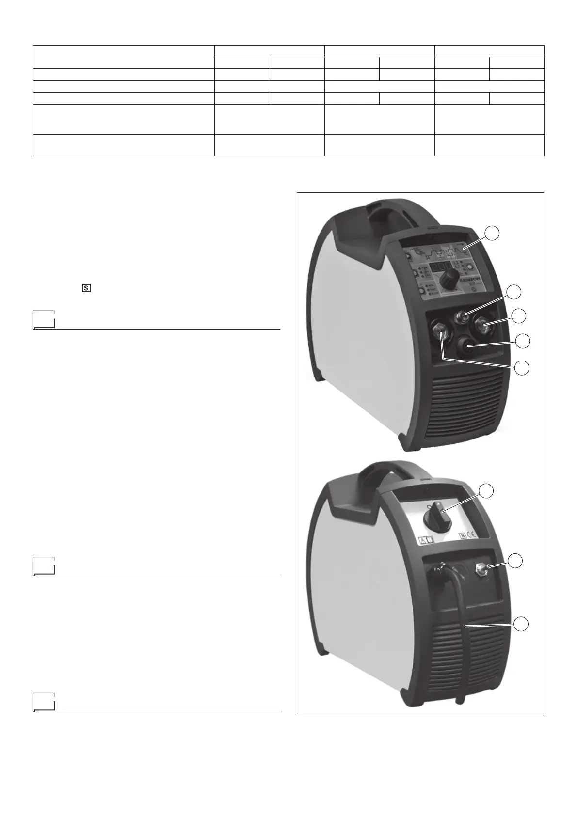
COMMAND AND CONTROL UNITS (Fig. A)
Pos. 1 RW21 / RW22 command and control panel.
Pos. 2 Positive pole quick connection.
Pos. 3 Fast coupling TIG torch gas tube.
Pos. 4 TIG weld auxiliary control connector (torch button, re-
mote controlpedal, etc.).
Pos. 5 Negative pole quick connection.
Pos. 6 Power supply switch.
In the “O” position the welder is off.
Pos. 7 Mains cable.
Pos. 8 Weld gas inlet coupling.
TIG welding
In the TIG process welding is achieved by melting the two metal
pieces to be joined, with the possible addition of material from the
outside, using an arc ignited by a tungsten electrode. The molten
bath and the electrode are protected by and inert gas (e.g. Argon,
and a flow rate of around 8-14 litres per minute). If necessary, to
complete the welded joint, suitable additional material is added.
2
4
5
6
1
8
7
3
FIG. A
Table 2
Model
RAINBOW 201 HF RAINBOW 182 HF PRO RAINBOW 202 HF PRO
TIG DC MMA TIG DC MMA TIG DC MMA
Power input @ I
2
Max kVA 8,5 9,0 6,9 8,3 8,5 9,0
Delayed fuse (I
2
@ 100%) A201620
Duty cycle @ X% (40°C) A 200 (25%)* 160 (30%)* 180 (25%)* 160 (20%)* 200 (25%)* 160 (30%)*
Supply connection cable
Length
Section
m
mm
2
2,5
2,5
2,5
2,5
2,5
2,5
Earth cable
Section mm
2
25 25 25
* Factor of efficiency