8
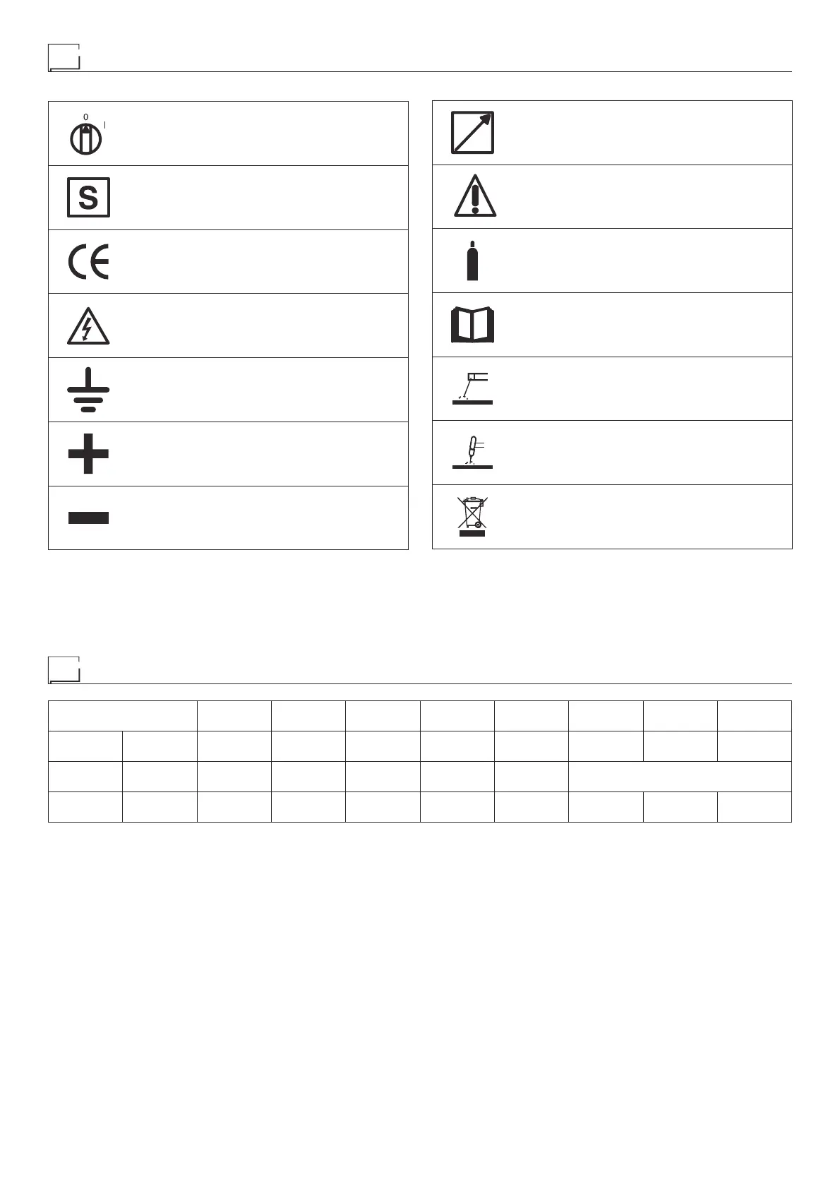
Meaning of graphic symbols on machine
Power supply switch
System for use in environments with increased
risk of electroshock
Product suitable for free circulation in the Euro-
pean Community
Danger! High voltage
Grounding
Positive pole snap-in connector
Negative pole snap-in connector
Connector for the remote control
Warning!
Fast coupling TIG torch gas tube
Before using the equipment you should carefully
read the instructions included in this manual
MMA welding
TIG welding
Special disposal
Key to the electrical diagram
•1 Capacitors •2 Remote control •3 TIG torch connector •4 Secondary diode
•5 Primary circuit rectifier •6 Digital display •7 DOWN button •8 Encoder •9
Gas solenoid valve •10 Pedal control potentiometer •11 Microswitch •12
Mains switch •13 Fan •14 Remote current potentiometer •15 Pedal con-
trol •16 TIG torch button •17 Primary IGBT circuit •18 Membrane keyboard
•19 EMC filter PCB •20 High frequency (HF) PCB •21 Digital interface PCB
•22 Primary Inverter PCB •23 Secondary circuit PCB •24 Secondary circuit
thermostat •25 HF transformer •26 TIG torch •27 Up / Down TIG torch •28
Main transformer •29 UP button
Colour key
Ar Orange
Az Sky Blue
Bc White
Bl Blue
Gg Grey
Gl Yellow
GV Yellow-Green
Mr Brown
Nr Black
Ro Pink
Rs Red
Vd Green
Vl Violet
Wiring diagram
•1 •2 •3 •4 •5 •6 •7 •8 •9
C11-12-13-24 CD 6 CT D1-2 D8-12 DD DW ED EVG
•10 •11 •12 •13 •14 •15 •16 •17 •18 •19
FPP FPS IL MV PD PSR 7 PT Q1-2-3-4 RF SF
•20 •21 •22 •23 •24 •25 •26 •27
SHF S-INT DIG S-INV SS THS THF TORCH TORCH UP/DOWN
•28 •29
TP UP