7
FOOT SWITCH PSR7
The foot switch replaces the torch button and the welding current
setting knob. The display will show the previous maximum weld
current value set on the welder. The pedal will adjust the welding
current from the minimum to this value (for further information see
the RW21 / RW22 control panel manual). Just turn the adjustment
knob on the welder to change the maximum output value.
NOTE:
•
To use the pedal control correctly, set the “welding mode” to
2-STROKE and then the welding parameters SLOPE UP time
to 0 sec., SLOPE DOWN time to 0 sec.
• When using the machine for TIG welding the operator can use
the torch button to start the weld and the pedal to regulate the
welding current remotely, provided the simultaneous use kit
(code CEA n° 460056) is used.
AIR AND/OR WATER-COOLED TORCH UP/ DOWN
The up/down torch replaces the current setting knob on the front
of the welder. Press right (+) and left (-) button to adjust the ac-
tive parameter. With this kind of torch, it is also possible to scroll
the saved programmes by pressing the two (+) and (-) buttons.
NOTE: The value shown on the display during welding represents
the effective current output with all types of control.
The digital control unit of the generator is fitted with a control rec-
ognition device which allows it to identify which device is connect-
ed and take action accordingly. To allow the command recognition
device to work correctly, connect (with the machine switched off)
the required accessory to the relative connector and then switch
on the welding machine with the on/off switch.
NOTE: It is not possible to memorize or open programmes
when the remote controls are connected (except for the torch
with UP/DOWN commands).
When the machine is doing a programmed weld, if a remote con-
trol command is activated (and the self-recognition procedure is
carried out), it exits programming automatically.
The pointing out of any difficulties
and their elimination
The supply line is attributed with the cause of the most common
difficulties. In the case of breakdown, proceed as follows:
1) Check the value of the supply voltage
2) Check that the power cable is perfectly connected to the plug
and the supply switch
3) Check that the power fuses are not burned out or loose
4) Check whether the following are defective:
• The switch that supplies the machine.
• The plug socket in the wall.
• The generator switch.
NOTE: Given the required technical skills necessary for the repair
of the generator, in case of breakdown we advise you to contact
skilled personnel or our technical service department.
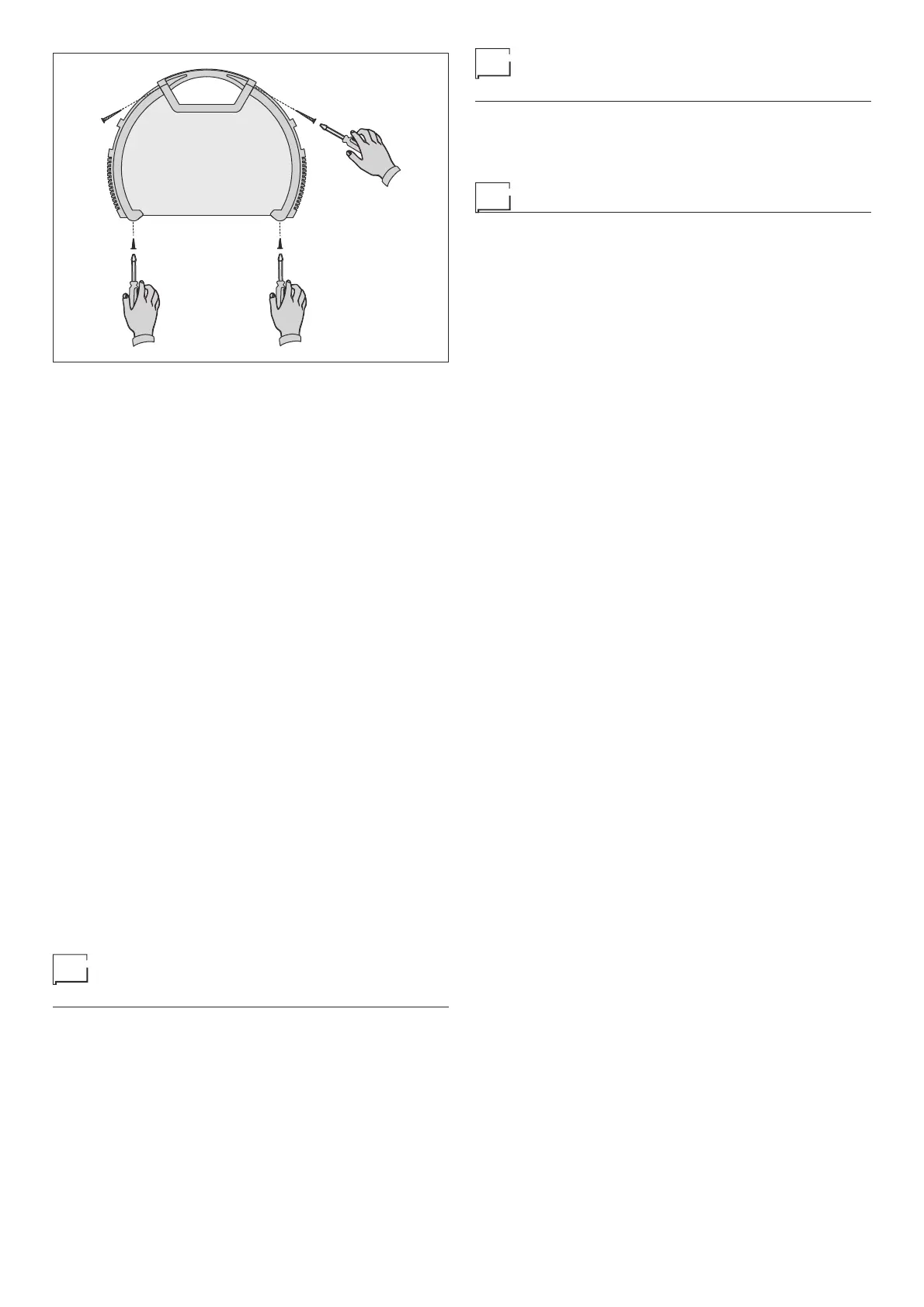
FIG. G
Procedure for welder assembly
and disassembly
Proceed as follows (Fig. G):
• Unscrew the 4 screws holding the front and back panels.
• Unscrew the 2 screws holding the handle.
• Proceed the other way round to re-assemble the welder.
Digital interface PCB replacement
Proceed as follows:
• Unscrew the 4 screws fastening the front rack panel.
• Remove the adjustment knob.
• Extract wiring connectors from digital interface PCB.
• Remove digital interface PCB by lifting it out of its supports.
• Proceed vice versa to assemble new digital interface PCB.