6
Electrode welding (MMA)
The welding electrode is used to weld most metals (various types
steel, etc.),for which rutilic and basic electrodes are used.
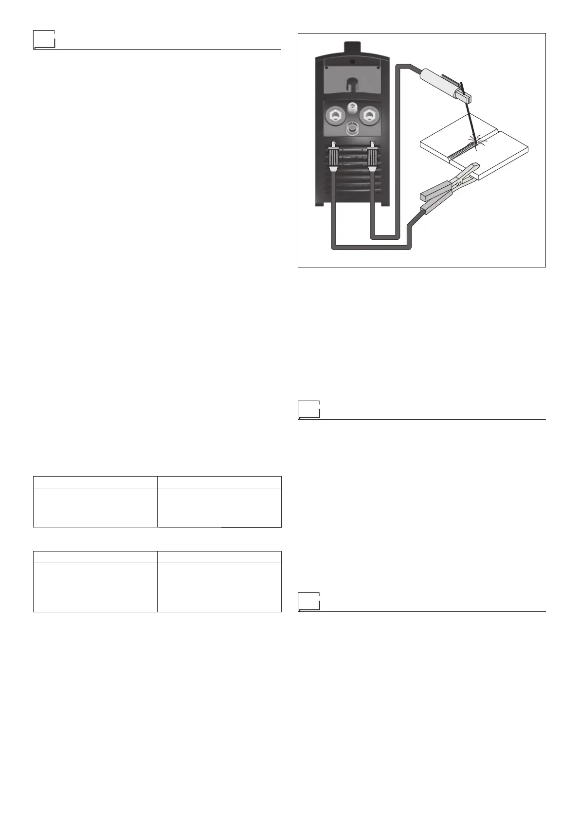
1) Connecting the welding cables (Fig. F):
Disconnect the machine from the mains power supply and con-
nect the welding cables to the output terminals (Positive and
Negative) of the welding machine, attaching them to the clamp
and ground with the polarity specified for the type of electrode
being used (Fig. F). Always follow the electrode manufactur-
er’s instructions. The welding cables must be as short as pos-
sible, they must be near to one another, positioned at or near
floor level. Do not touch the electrode clamp and the ground
clamp simultaneously.
2) Switch the welding machine on by moving the power supply
switch to I (Pos. 6, Fig. A).
3) Make the adjustments and select the parameters on the con-
trol panel (for further information see the RW21 / RW22 con-
trol panel manual).
4) Carry out welding by moving the torch to the workpiece. Strike
the arc (press the electrode quickly against the metal and then
lift it) to melt the electrode, the coating of which forms a protec-
tive residue. Then continue welding by moving the electrode
from left to right, inclining it by about 60° compared with the
metal in relation to the direction of welding.
PART TO BE WELDED
The part to be welded must always be connected to ground in or-
der to reduce electromagnetic emission. Much attention must be
afforded so that the ground connection of the part to be welded
does not increase the risk of accident to the user or the risk of dam-
age to other electric equipment. When it is necessary to connect
the part to be welded to ground, you should make a direct con-
nection between the part and the ground shaft. In those countries
in which such a connection is not allowed, connect the part to be
welded to ground using suitable capacitors, in compliance with the
national regulations.
WELDING PARAMETERS
Table 4 shows some general indications for the choice of elec-
trode, based on the thickness of the parts to be welded. The val-
ues of current to use are shown in table 5 with the respective
electrodes for the welding of common steels and low-grade al-
loys. These data have no absolute value and are indicative data
only. For a precise choice follow the instructions provided by the
electrode manufacturer.
Table 4
WELDING THICKNESS (mm) Ø ELECTRODE (mm)
1,5 ÷ 3
3 ÷ 5
5 ÷ 12
≥ 12
2
2,5
3,2
4
Table 5
Ø ELECTRODE (mm) CURRENT (A)
1,6
2
2,5
3,2
4
30 ÷ 60
40 ÷ 75
60 ÷ 110
95 ÷ 140
140 ÷ 190
The current to be used depends on the welding positions and the
type of joint, and it increases according to the thickness and di-
mensions of the part.
The current intensity to be used for the different types of welding,
within the field of regulation shown in table 5 is:
• High for plane, frontal plane and vertical upwards welding.
• Medium for overhead welding.
•
Low for vertical downwards welding and for joining small pre-
heated pieces.
FIG. F
A fairly approximate indication of the average current to use in
the welding of electrodes for ordinary steel is given by the follow-
ing formula:
I = 50 × (Øe - 1)
Where:
I = intensity of the welding current
Øe = electrode diameter
Example:
For electrode diameter 4 mm
I = 50 × (4 - 1) = 50 × 3 = 150A
Maintenance
ATTENTION: Before carrying out any inspection of the inside of
the generator, disconnect the system from the supply.
SPARE PARTS
Original spare parts have been specially designed for our equip-
ment. The use of non-original spare parts may cause variations in
performance or reduce the foreseen level of safety.
We decline all responsibility for the use of non-original spare parts.
GENERATOR
As these systems are completely static, proceed as follow:
•
Periodic removal of accumulated dirt and dust from the inside
of the generator, using compressed air. Do not aim the air jet
directly onto the electrical components, in order to avoid dam-
aging them.
• Make periodical inspections in order to individuate worn cables
or loose connections that are the cause of overheating.
Optional
RAINBOW 201 HF / 182 HF PRO / 202 HF PRO generators can
be fitted with various remote control devices and accessories.
The remote controls can be only used in the 2-STROKE and
4-STROKE welding modes.
MANUAL REMOTE CONTROL CD6
WARNING: When using the machine for TIG welding it is OBLIGA-
TORY to use the kit for simultaneously use – CEA code n° 460056.
Weld current can be measured at a distance by connecting up this
control. The display will show the previous maximum weld cur-
rent value set on the welder. The remote control will adjust weld-
ing current from the minimum to this value (for further information
see the RW21 / RW22 control panel manual). Just turn the adjust-
ment knob on the welder to change the maximum output value.