M
Mathew BlairAug 4, 2025
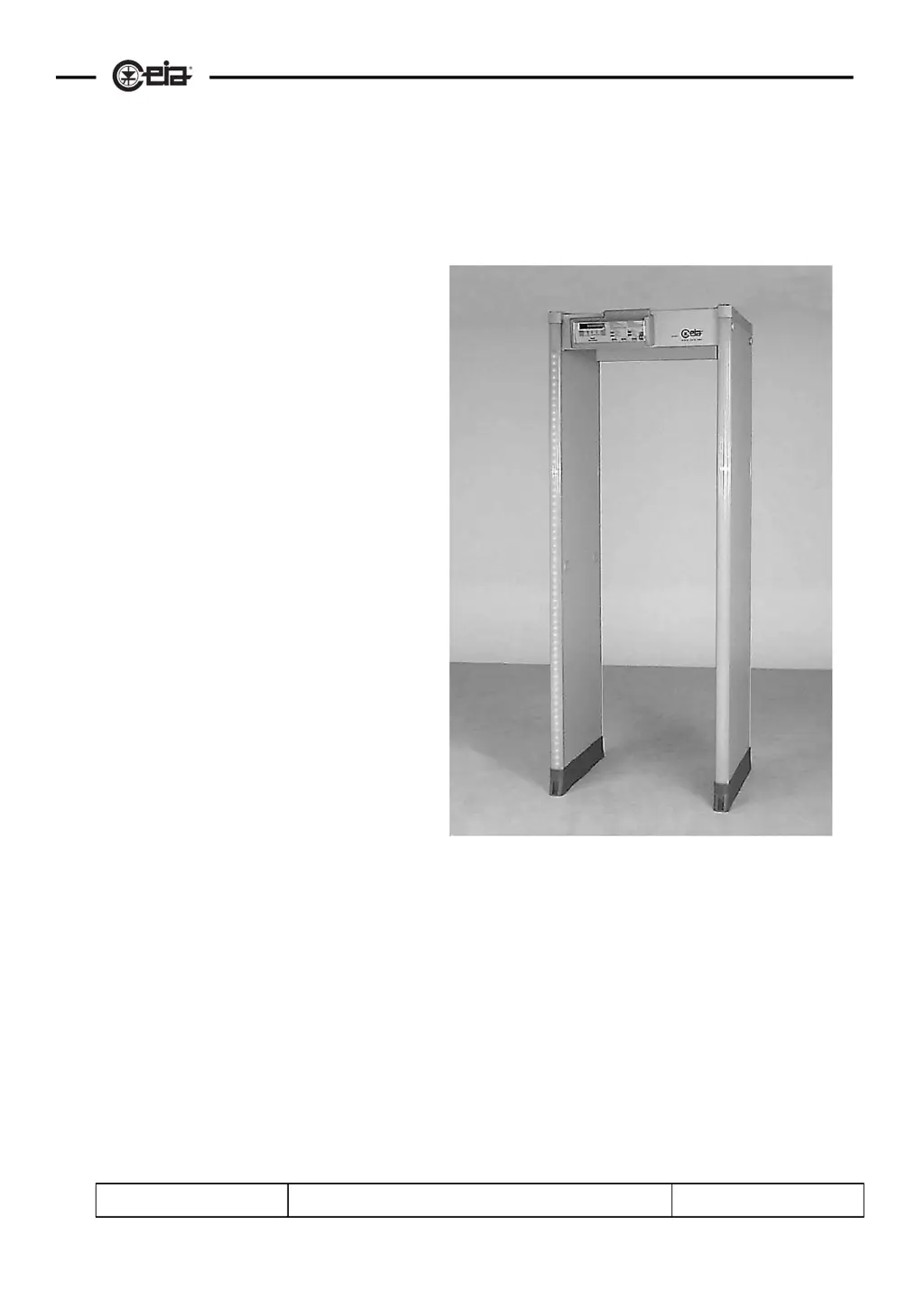
What to do if the display is off on my Ceia Metal Detector with emergency batteries?
- MMarc MorrisAug 4, 2025
If you have a Ceia Metal Detector and the display is off, and it is a model with emergency batteries, connect the equipment to the mains supply to recharge the batteries.